vertical_adjustment
Utility “Add Vertical Control” adds elevation information based on MOLA heights to the tie points measured in the Relative Orientation. The tie points are then flagged as Z-Control points in the ground point file (GPF).
The “Add Vertical Control” utility will auto-fill the input files based
on the <ProjectName> listed. If the grayed out entries are
correct, simply check the boxes next to each field to confirm them.
Otherwise, press the buttons associated with each field to select the
correct files. The following steps detail the procedure.
-
From the SOCET SET menu bar, select
USGS Tools > Add Vertical Control.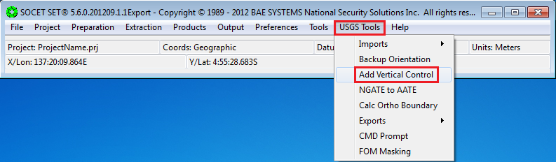
-
If the project file listed in the
Project Filefield is correct, check the box next to the Project File field to confirm it. Otherwise, press the “Project File…” button to bring up the list of projects and select the project from the list.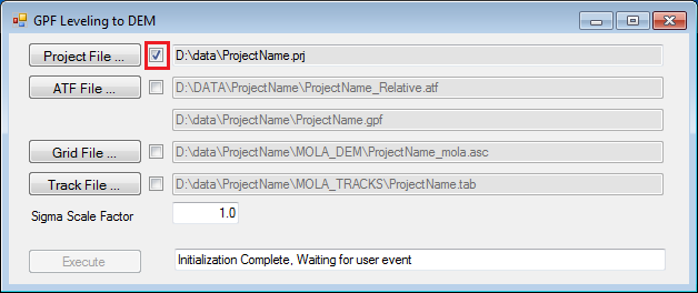
-
The input ATF File should be
<ProjectName>_Relative.atf. Either confirm the “ATF File” listed is correct by checking its check box, or press the “ATF File…” button to select<ProjectName>_Relative.atf.(The Ground Point File (GPF) is also listed. It should be<ProjectName>.gpf.)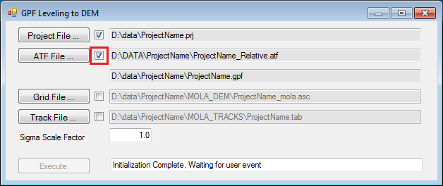
-
The input Grid File should be
<ProjectName>_mola.asclocated in theMOLA_DEMfolder. Either confirm theGrid Filelisted is correct by checking its check box, or press theGrid File…button to selectD:\\DATA\\<ProjectName>\\MOLA_DEM\\<ProjectName>_mola.asc.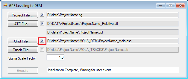
-
The input Track File should be
<ProjectName>.tablocated in theMOLA_TRACKSfolder. Either confirm theTrack Filelisted is correct by checking its check box, or press theTrack File…button to selectD:\\DATA\\<ProjectName>\\MOLA\_TRACKS\\<ProjectName>.tab. (Note: If a Track File does not exist, keep the Track File field blank and check the confirmation box.)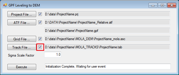
-
Press
Execute. (If the Execute button is not activated please check the confirmation checkboxes.)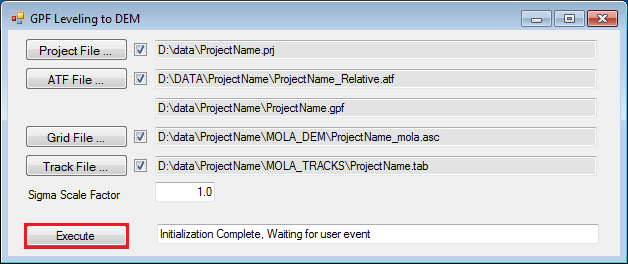
-
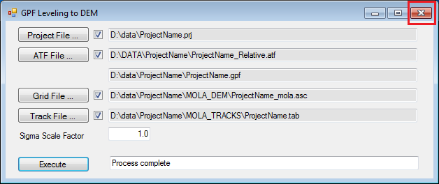
Close the window via the upper-right close button.
-
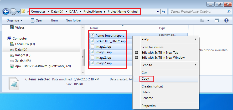
Open Windows Explorer. Navigate to
D:\\DATA\\<ProjectName>\\<ProjectName>_Original, select all the files in the folder, and Copy them.Note: There are more than image support files in this folder, but there is no harm copying the extraneous files, and it is quickest to just select all the files.
-
Move up one folder so you are now in
D:\\DATA\\<ProjectName>, and paste the files.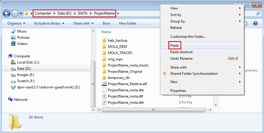
-
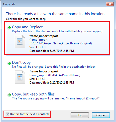
In the pop-up window, check the box in the lower left corner to “do this for the next 3 conflicts”, then select “Copy and Replace”.
-
Close the Windows Explorer window.
-
From the SOCET SET menu bar, select
Preparation > Multi-Sensor Triangulation.
-
Select
File > Save Triangulation File As…in the Automated Triangulation window.Note:
<ProjectName>\_Relative.atfwas automatically loaded. For the Vertical Adjustment to MOLA, no changes will be made to the Setup, however, we will provide a more meaningful name to the ATF file.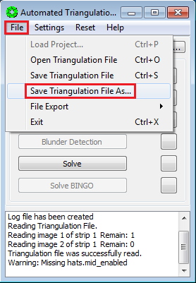
-
In the pop-up window, enter
<ProjectName>_Rel_VertCtrl, and pressOK.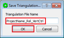
-
Press
Solvein the Automated Triangulation window.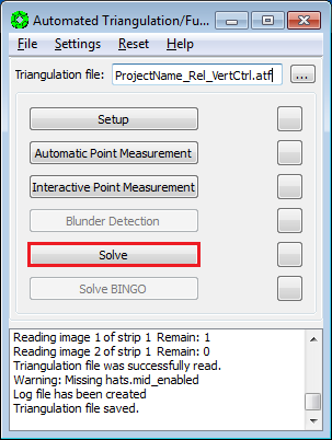
-
The
Simultaneous Solvewindow will open, along with aBackuppop-up window. PressYeson the pop-up to overwrite back up files.
-
In the
Simultaneous Solvewindow, pressStartto perform the bundle adjustment.
-
Once the adjustment is completed, evaluate the errors in the adjustment.
An acceptable solution has (1) an Image (pixels) RMS of ~0.6 or less, and (2)no individual point measurement has an error greater than 2 pixels.
Press
Resultsbutton in the Simultaneous Solve window to review error of individual point measurements.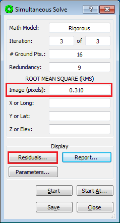
-
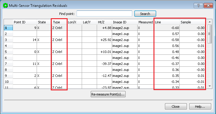
In the Vertical Adjustment procedure, all points are now Z-Control, so inspecting the top of the list will suffice.
-
If points have pixel errors greater than 2.0 pixels, SKIP TO: 18.4 Point Weights Refinement. Otherwise, continue to the next step.
-
If the image RMS is < ~0.6 pixels, and the maximum point measurement error is < 2.0 pixels, then Press
Closeon the Multi-Sensor Triangulation Residuals window.
-
Press
Saveon the simultaneous solve window.
-
Press
Yeson the Done pop-up window.
-
Press
Closeon the Simultaneous Solve window.
-
Select
File > Exiton the Automatic Triangulation window.
Vertical Adjustment is now complete!
-
SKIP: 18.4 Point Weight Refinement and 18.5 Point Re-Measurement Process, GO TO: 18.6 Re-Load Images.
Continuing from 18.3 Bundle Adjustment…
The previous Relative Orientation adjustment should have met the criteria of the Image RMS less than ~0.6 pixels, and individual point errors less than 2.0 pixels. The only change since the Relative Orientation is that we added elevation estimates to the measured points. If the Image RMS < ~0.6 pixels; Point Errors < 2.0 pixels criteria is not met now, the cause is most likely that the weights (i.e., Accuracy Values) assigned to the elevation estimates by “Add Vertical Control” are too stringent. We will first evaluate and adjust Accuracy values. If the criteria of an acceptable solution is still not met after another bundle adjustment (Solve), then we will re-measure points.
-
From the
Multi-Sensor Triangulation Residualswindow, record (on a piece of paper) the Point ID’s of the points with > 2.0 pixel line and/or sample errors. Then close the Residuals window.
-
Press
Closeon the Simultaneous Solve window. (Do not pressSave.)
-
Press
Noto Saving Files in the Done pop-up window.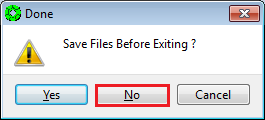
-
Press
Interactive Point Measurementon the Automated Triangulation window.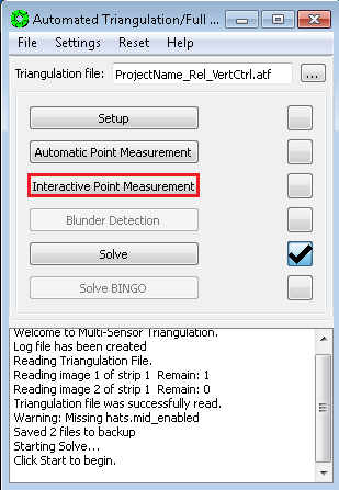
-
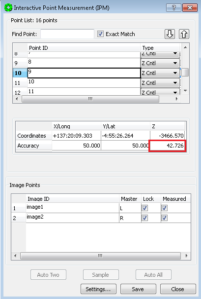
For each point recorded on your list:
a. Use the Scroll Bar to the right of the point list, and scroll to the point. Click on the point’s Point ID to select it.
b. IPM will move the stereo display to the selected point. Look at the measurement in stereo. If the point is on a slope, the Accuracy assigned to the Z coordinate may be too tight. We suggest you increase the Accuracy by approximately a factor of 2: double click in the Accuracy field for Z, delete the old value and type in the new value, then press the enter key.
-
When you are done updating Accuracy values, press
SavethenCloseon the IPM window.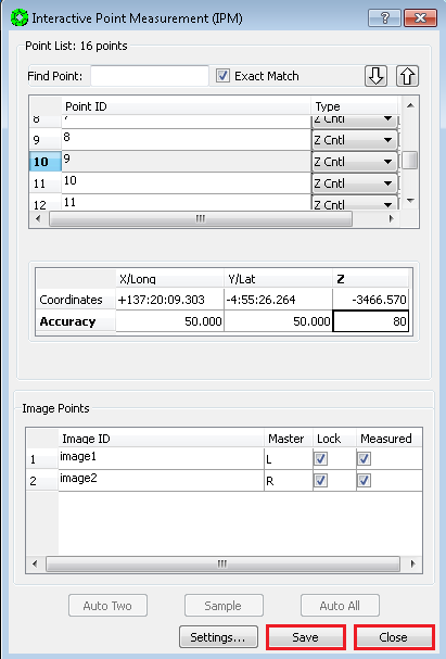
-
Press
Solveon the Automated Triangulation window.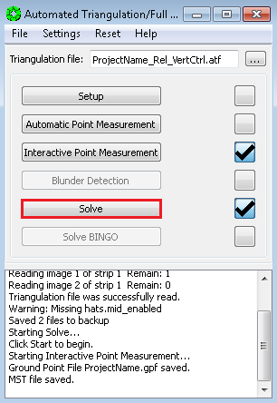
-
Press
Starton the Simultaneous Solve window.
-
Press
Residualson the Simultaneous Solve window and make sure no individual point has an error greater than 2 pixels. -
If the solution continues to have points with larger than 2 pixel errors, the problem may be a bad measurement(s), so GO TO 18.5 Point Re-Measurement Process. Otherwise, continue to the next step.
-
If the image RMS is < ~0.6 pixels, and the maximum point measurement error is < 2.0 pixels, we will exit Multi-Sensor Triangulation, and re-enter it in order to refresh the values stored in computer memory. First press
Closeon the Multi-Sensor Triangulation Residuals window.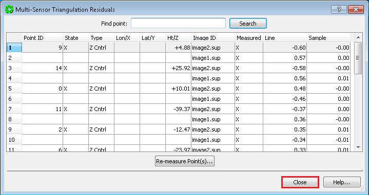
-
Press
Closeon the Simultaneous Solve window (Do Not PressSave.)
-
Press
Noto Saving Files in the Done pop-up window.
-
Select
File > Exiton the Automatic Triangulation window.
-
Re-enter MST: From the SOCET SET menu bar, select
Preparation > Multi-Sensor Triangulation.
-
Press
Solveon the Automatic Triangulation window. (The triangulation file,<ProjectName>_Rel_VertCtrlshould load automatically.)
-
Press
Yeson the pop-up to overwrite back up files.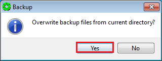
-
Press
Starton the Simultaneous Solve window.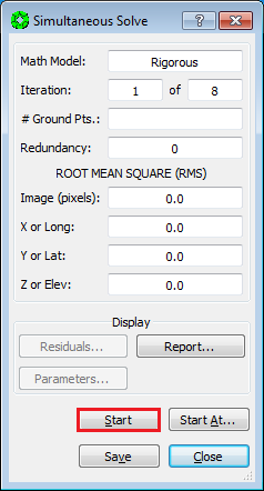
-
If the Image (pixels) RMS is < ~0.6 pixels, Press
Saveon the Simultaneous Solve window.
-
Press
Yeson the Done pop-up window.
-
Press
Closeon the Simultaneous Solve window.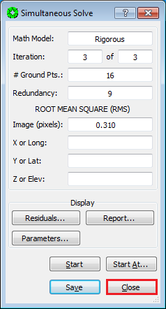
-
Select
File > Exiton the Automatic Triangulation window.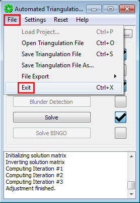
Vertical Adjustment is now complete!
-
SKIP: 18.5 Point Re-Measurement Process, GO TO: 18.6 Re-Load Images.
Continuing from 18.4 Point Weights Refinement…
-
On the
Multi-Sensor Triangulation Residualswindow, Left-Click on the Point ID(s) of the points to re-measure. (Hold the Control Key down to select multiple points.) Then pressRe-measure Point(s)…. The re-measure point window will now open with the points selected.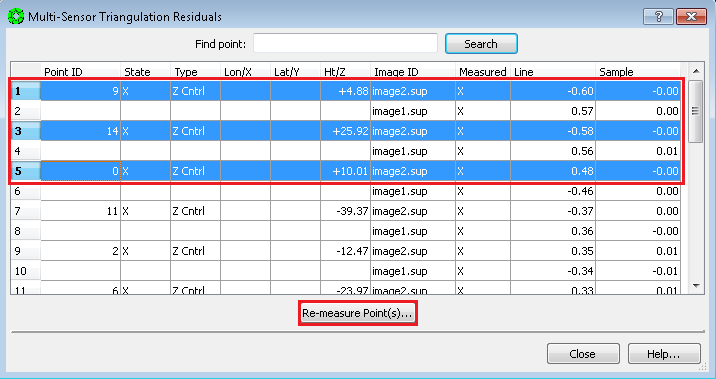
-
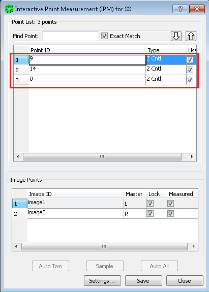
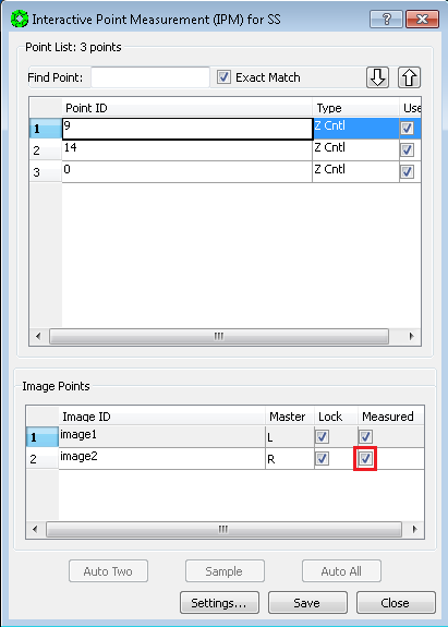
Left-Click on the point to re-measure. The View 1 (stereo display) window will display the current point measurement.
-
Un-check the Measured box for the Right image only, to remove parallax.
NOTE: Relocating the point is not advised because there is now an elevation estimate associated with the point.
-
Clear the parallax by moving the Right image only (i.e., put the dot on the ground).
-
Press
Sampleto collect the point measurement.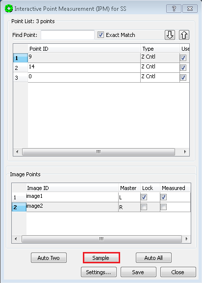
-
Press
Savewrite the measurement to disk.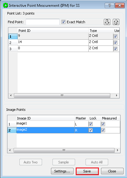
-
Repeat re-measurement process for remaining points in the list. (Go back to step 2.)
-
After points in the list are re-measured press
Close.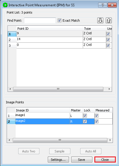
-
Press
Closeon the Multi-Sensor Triangulation Residuals window.
-
Press
Starton the Simultaneous Solve window.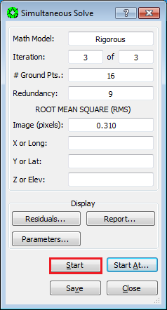
-
Press
Residualson the Simultaneous Solve window and make sure no individual point has an error greater than 2 pixels.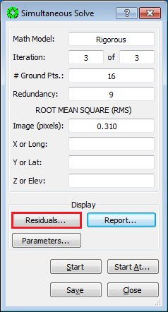
-
If there are points with larger than 2 pixel errors, repeat the Point Re-Measurement Process starting from step 1.
-
If the image RMS is < ~0.6 pixels, and the maximum point measurement error is < 2.0 pixels, we will exit Multi-Sensor Triangulation, and re-enter it in order to refresh the values stored in computer memory. First press
Closeon the Multi-Sensor Triangulation Residuals window.
-
Press
Closeon the Simultaneous Solve window (Do Not PressSave.)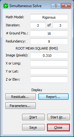
-
Press
Noto Saving Files in the Done pop-up window.
-
Select
File > Exiton the Automatic Triangulation window.
-
Re-enter MST: From the SOCET SET menu bar, select
Preparation > Multi-Sensor Triangulation.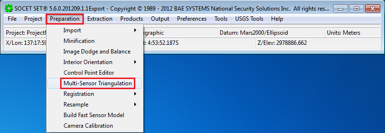
-
Press
Solveon the Automatic Triangulation window. (The triangulation file,<ProjectName>_Rel_VertCtrlshould load automatically.)
-
Press
Yeson the pop-up to overwrite back up files.
-
Press
Starton the Simultaneous Solve window.
-
If the Image (pixels) RMS is < ~0.6 pixels, Press
Saveon the Simultaneous Solve window.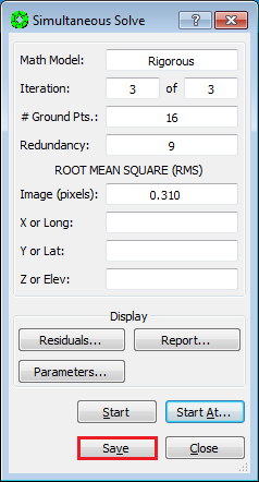
-
Press
Yeson the Done pop-up window.
-
Press
Closeon the Simultaneous Solve window.
-
Select
File > Exiton the Automatic Triangulation window. .
.Vertical Adjustment to MOLA is now complete!
After the Vertical Adjustment to MOLA is complete, it is necessary to re-Load the images in order to view them with the results of the adjustment.
-
From the SOCET SET menu bar, select
File >Load Images`.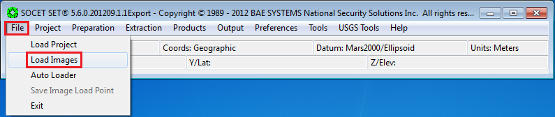
-
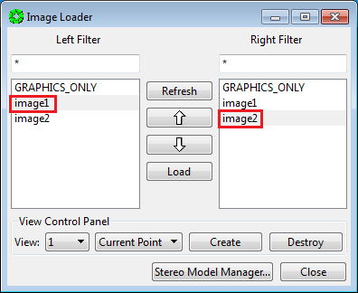
In the Image Loader window, select the Left and Right Image to display by clicking on the image id in the Left and Right panels. (Selected images will be highlighted.)
-
Under
View Control Panelsettings: Ensure thatView = 1and thatLoad Pointis selected.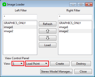
-
Press
Load.

-
Press
Close.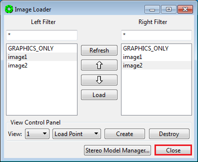
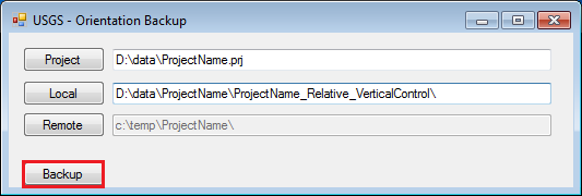
At this point, it is prudent to backup the project data in order to have a re-entry point for the up-coming Absolute Orientation of the stereo images to MOLA.
-
From the SOCET SET menu bar, select
USGS Tools > Backup Orientation.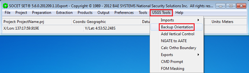
-
Make sure the current project name is listed in the Project field. If not, press “Project” to select the current project, then press
OK. (Otherwise the backup will be made in, and for, the wrong project!)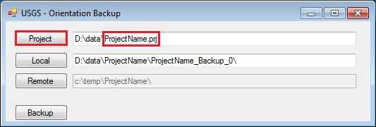
-
Replace
Backup_0withRelative_VerticalControlin theLocalfolder name field. The backup folder will be named<ProjectName>_Relative_VerticalControl.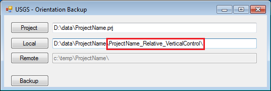
-
Press
Backup.