generate_ortho
For HiRISE, it is useful to generate an orthoimage of each image in the stereo pair at both (a) 1 m resolution, exactly matching the DTM, and (b) 0.25 m resolution to preserve the maximum information in the images.
We use the controlled images (not the epipolar rectified images with _r
and _l extensions), without enhancements, as input for
orthorectification.
-
Make sure there are no image enhancement files associated with the input image in the project data directory before proceeding. Enhancement files are stored in the Project’s data folder (i.e.,
D:\\DATA\\<ProjectName>) and have an extension of .enh.a. If there are enhancement files, delete them or move them somewhere else temporarily.
b. We do this because image brightness/contrast adjustments in the enhancement files will be applied to the orthorectified image upon creation. We are keeping track of the stretch to 8-bit when processing HiRISE images for SOCET SET import so that we can get back to radiometric values if needed. Appling an arbitrary stretch through enhancement files will defeat this purpose.
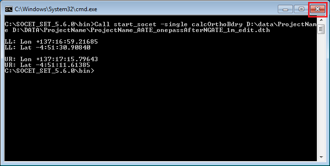
So that a 1:1 correspondence between the DTM and the 1 m orthoimages is maintained in software packages such as ISIS and Photoshop, we run “calc Ortho Boundary” to calculate Lower Left and Upper Right georeferencing corner coordinates to be used as input for orthophoto generation.
-
From the SOCET SET menu bar, select
USGS Tools > Calc Ortho Boundary.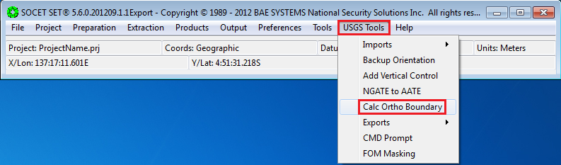
-
If the project file listed in the Project File field is correct, check the box next to the Project File field to confirm it. Otherwise, press the
Project File…button to bring up the list of projects and select the project from the list.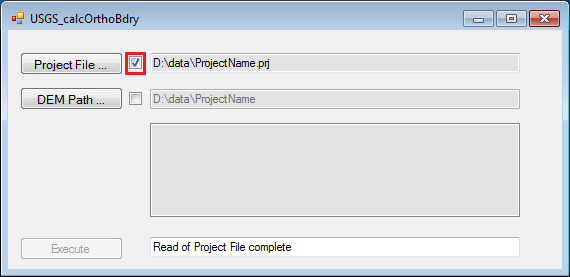
-
The path listed in the DEM Path field should be the path to the current project’s data folder. If the path is correct, check the box next to the DEM Path field to confirm it. Otherwise, press
DEM Path…, and navigate to the project’s data folder to select it.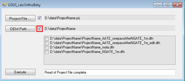
-
Upon confirming the DEM Path, the available DTMs in the project will be listed. Select the final edited version of the DTM by clicking on its check box twice. Then press
Execute.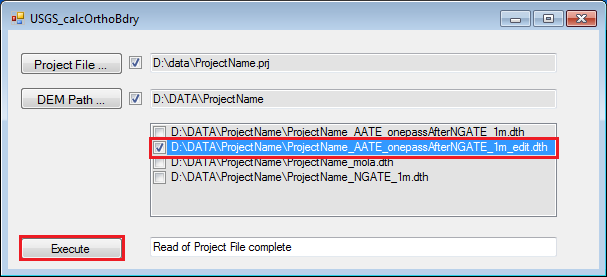
-
Close the Command Prompt Window that came up.
-
The results of Calc Ortho Boundary is written to a log file in the project’s data folder. The log name is of the form
calcOrthoBdry_<the_input_DTM_name>.log.
Note: Generation of 1 m orthoimages takes 1 to 2 hours. Generation of 0.25 m orthoimages can take up to 12 hours each. (These time estimates are based on the current processors configuration at the Planetary Photogrammetry Facility.) For Guest Facility Users or Astrogeology staff, doing production work, see Appendix: A-5.3 Orthophoto GenerationBatch Processing for how to run Orthophoto in batch.
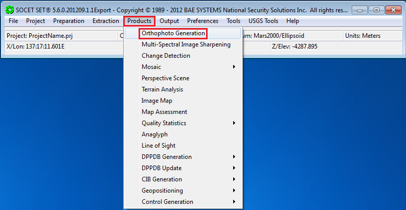
From the SOCET SET menu bar, select Products > Orthophoto Generation.
-
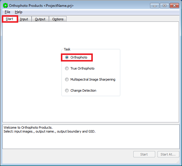
In the Start Tab, make sure Task is set to Orthphoto.
-
Press the
Inputtab.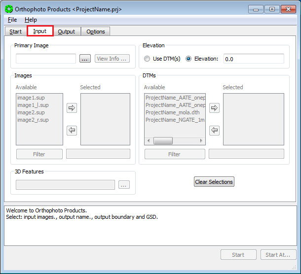
-
Press the button next to the
Primary Imagefield.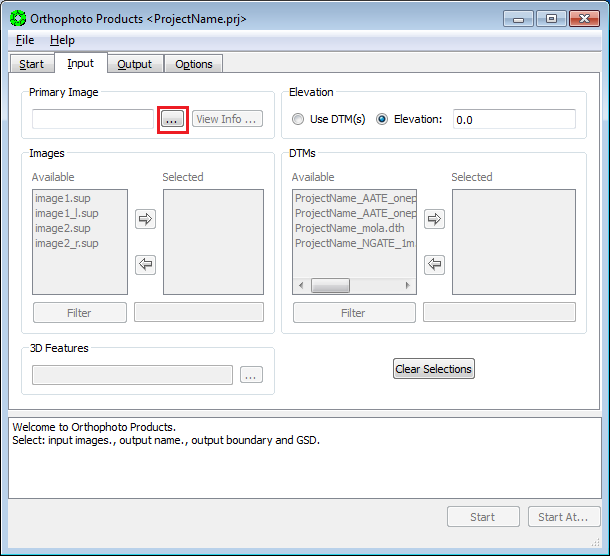
-
In the pop-up window, select the image to orthorectify. Then press
OK. Do not select the epipolar rectified images.
-
Press the radio button for
Use DTM. Then, from the list ofAvailableDTMs, move the final (edited) DTM to theSelectedlist via the arrow button.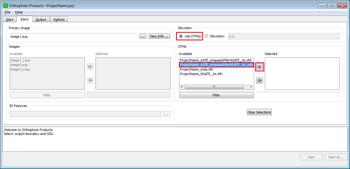
-
Press the
Outputtab.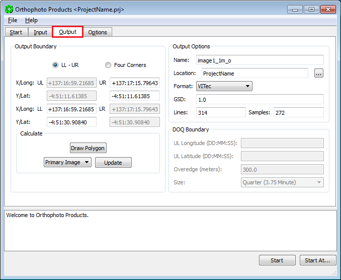
-
Bring up a Windows/File Explorer window. Navigate to
D:\\DATA\\<ProjectName>and opencalcOrthoBdry_<DTMname>.logwith a text editor.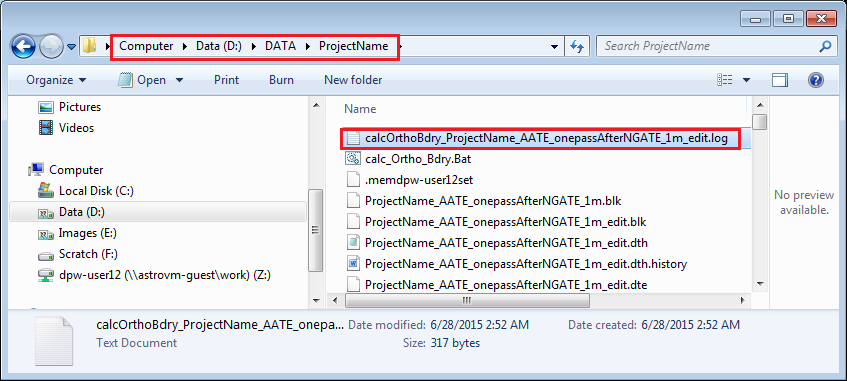
-
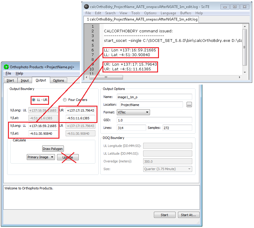
In the Output Boundary Section of the Orthophoto window:
a. Turn on radio button LL-UR in the Output Boundary section.
b. Then copy-and-paste the LL and UR coordinates from
calcOrthoBdry_<DTMname>.loginto the LL and UR boxes. Do not press “Update” after entering LL and UR coordinates.Note: You only need to copy-and-paste the LL and UR coordinates once…the values will hold for multiple orthophoto setups.
-
In the Output Options Section:
a. Change the default `Name` of the orthoimage from
`<image>_o` to `<image>_1m_o` or
`<image>_25cm_o`, as appropriate.
b. Make sure the `Location` is set to the project’s image location,
c. Use the drop down arrow to set `Format` to Vitec.
> Note: We’ve had problems with TIFF-Tiled format when
orthorectifying large images.
d. Type in the `GSD` (ground sample distance) of the desired
resolution (e.g., 1 m or 0.25 m). Then press the enter key.

-
Press the
Optionstab.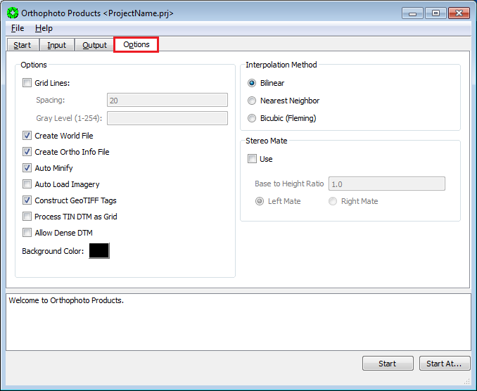
-
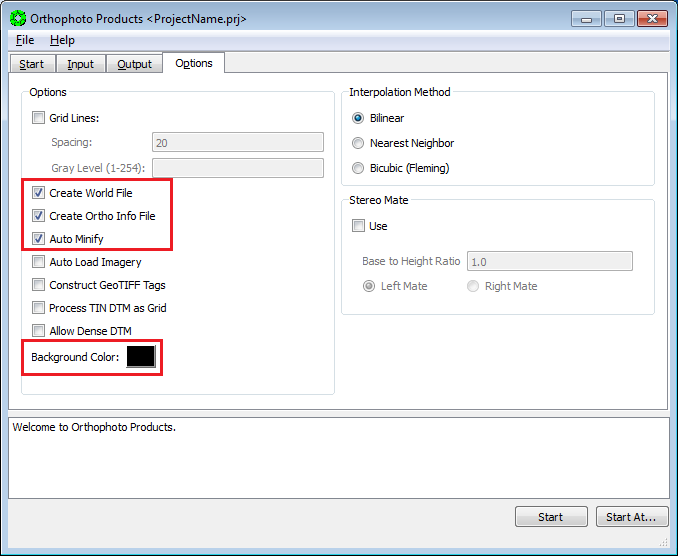
In the Options Section:
a. Check the boxes for:
i. Create World File.
ii. Create Ortho Info File.
iii. Auto Minify.
b. Set the Background Color to Black: Click on box displaying background color to cycle through color options.
-
Press
Startat the bottom of the Orthophoto window.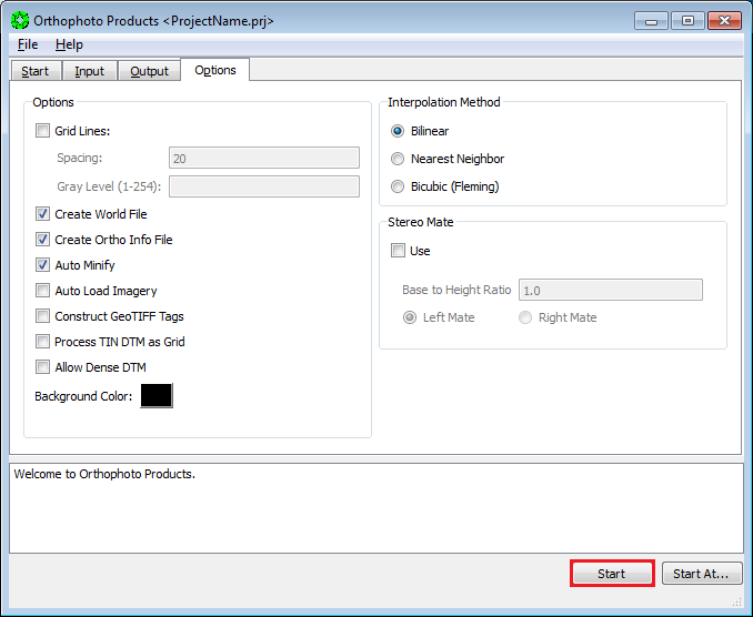
-
Go To 23.3.2 Orthophoto Generation, and repeat the steps for next orthoimage.
-
Close the Orthophoto Products window when all orthoimages are generated.