Soma Reconstruction
- Soma Reconstruction Toolbox
- Soma Reconstruction Methods
- Rendering Soma
- Exporting a Soma Mesh
- References
Due to the fuzzy definition of the soma, the relevant information contained in generic morphology skeletons that describe the soma is usually insufficient to reconstruct a realistic representation of it (Luengo-Sanchez et al., 2015). The soma is merely represented by a centroid, a radius (that approximates the average distance between this centroid and the initial segments of each neurite) and a projective profile that is traced on a two-dimensional plane. In certain studies, the soma is not modeled based on the reported data in the morphological skeleton, but rather represented by an implicit surface for convenience. Therefore, the reconstruction of even an approximation of the soma contour is quite challenging. Recent methods have been presented to provide a univocal definition of the somata, allowing automated characterization of neurons and accurate segmentation of three-dimensional somata profiles measured at multiple depths of fields during the tracing procedure.
The Soma Reconstruction Toolbox is added to allow the generation of more accurate somata profiles relying on their two-dimensional contours and the starting locations of their neurites. We use two methods to build three-dimensional profiles of the soma. The first approach uses what is called MetaBalls to build a rough approximation of the actual profile. The other method builds a more plausible soma profile using Soft Body objects. The process simulates the progressive reconstruction of the soma using Hooke’s law and mass spring models. The idea has been adapted from a recent study (Brito et al., 2013) and implemented in Blender using its physics engine (Abdellah et al., 2017b).
We therefore integrated this module into NeuroMorphoVis to provide a convenient tool to validate and compare the somata obtained by segmenting a microscopic stack with the ones extracted from three-dimensional contours.


When you toggle (or click on) the Soma Toolbox tab highlighted above, the following panel, or a similar one depending on the version of NeuroMorphoVis, will appear.

In the following sections, we describe all the different parameters of each method.
This toolbox provides two methods for reconstructing somata profiles:
- MetaBalls
- SoftBody
The MetaBalls method is used to reconstruct a rough estimate of the soma shape in real-time. This approoximation is evidently better than a symbolic representation with a sphere. The approach is extremely fast compared to the SoftBody method and can be extremely useful for visualizing large circuits with thousands of neurons.

This option can be set in the configuration file as follows:
## Soma reconstruction method
SOMA_RECONSTRUCTION_METHOD=meta-ballsThe resolution of the meta ball object defines the quality of the reconstructed soma mesh. The less this value is the better the final mesh. Acceptable range for this parameters is 0.05 - 2.0, however using lower values than 0.2 reconstructs the soma in several seconds.
The following images show a comparison between three somata reconstructed with 0.1, 0.5 and 0.9 resolutions.
| 0.1 | 0.5 | 0.9 |
|---|---|---|
|
 |
 |
Range: 0.05 - 2.0
Default Value: 0.2
This option can be adjusted in the configuration file as follows:
## MetaBall resolution
# Acceptable range (0.05 - 2.0), by default 0.2.
SOMA_META_BALL_RESOLUTION=0.2The SoftBody method uses a physically-based approach to reconstruct an accurate shape of the soma using the physics engine in Blender. This method takes few seconds to build the soma, but it is more accurate than the MetaBalls method. Note that this method does not preserve the final volume of the reconstructed soma shape. It only creates a highly realistic shape of the soma mainly for machine learning purposes.

This option can be set in the configuration file as follows:
## Soma reconstruction method
SOMA_RECONSTRUCTION_METHOD=soft-body
The SoftBody reconstruction method can build somata meshes based on (i) the three-dimensional points of the starting samples of the arbors connected to it, (ii) the two-dimensional profile points reported in the soma file or (iii) a mixture of all the points. Moreover the simulation has four principal parameters including the soft body Stiffness, the number of steps used to perform the simulation, the subdivisions of the initial sphere and a user-defined scale factor to adjust the initial radius of the ico-sphere used to reconstruct the soma shape. These parameters are shown below.
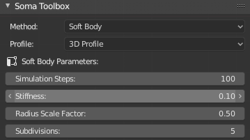
This version of NeuroMorphoVis has implemented three different methods to reconstruct three-dimensional somata profiles:
- 2D Profile: This method uses only the profile points that are reported in the morphology files to reconstruct the soma from an ico-sphere, whose radius is set to the mean soma radius.

- 3D Profile: This method uses the starting points of each root arbor to deform an ico-sphere. This is the deafult reconstruction method.

- Mixed: This is a combined method of the two previous ones. The pulling occurs towards the profiles points and the starting points of each neurite connected to the soma.

This option can be adjusted in the configuration file as follows:
## Softbody profile
# Use '3d', '2d' or 'mixed', by default '3d'.
SOMA_SOFT_BODY_PROFILE=3d
Soft body simulation is used in general for simulating soft deformable objects. It was designed primarily for adding secondary motion to animation, like jiggle for body parts of a moving character. It also works for simulating more general soft objects that bend, deform and react to forces like gravity and wind, or collide with other objects. The simulation works by combining existing animation on the object with forces acting on it. There are exterior forces like gravity or force fields and interior forces that hold the vertices together. This way you can simulate the shapes that an object would take on in reality if it had volume, was filled with something, and was acted on by real forces. NeuroMorphoVis uses soft body simulation to deform an initial ico-sphere into an object that can reflect or approximate a three-dimensional profile of the soma. Further details about soft body simulation can be found in this link.
The number of Simulation Steps required to generate the final mesh. More steps are better to converge as shown in the following comparison. Acceptable range is 50 - 200 and the default value is 100 steps.
| 50 | 100 | 200 |
|---|---|---|
 |
 |
 |
Range: 50 - 200
Default Value: 100
This option can be adjusted in the configuration file as follows:
## Softbody number of simulation steps
# Acceptable range 50 - 200, 100 by default.
SOMA_SOFT_BODY_STEPS=100The Stiffness slider controls the spring stiffness of the soft body object. A low value creates very weak springs (more flexible "attachment" to the goal), a high value creates a strong spring (a stiffer "attachment" to the goal). The animations below demonstrate how stiffness variations impact the progressive reconstruction of the soma and its final profile.
| 0.01 | 0.10 | 0.99 |
|---|---|---|
 |
 |
 |
Range: 0.01 - 0.99
Default Value: 0.1
This option can be set in the configuration file as follows:
## Soma stiffness
# Acceptable range (0.01 - 0.99), by default 0.10.
SOMA_STIFFNESS=0.10-
We have gone through many trial and error iterations to test some other parameters of the soft body object to yield a plausible shape. However, the user does not have control to any of them. These values are as follows:
- Garvity 0.0
- Goal Max 0.1
- Goal Min 0.7
- Goal Default 0.5
-
Soft bodies work especially well if the objects have an even vertex distribution. You need enough vertices for good collisions. You change the deformation (via the Stiffness slider) if you add more vertices in a certain region.
The initial ico-sphere used to reconstruct the final soma profile can be scaled before the pulling action is applied to it during the simulation. This scaling will impact the final profile shape as shown in the following comparison where 0.25, 0.50 and 0.9 scale factors are used. The Radius Scale Factor parameter is used to apply this scale from the GUI.
| 0.25 | 0.50 | 0.90 |
|---|---|---|
 |
 |
 |
Range: 0.25 - 0.9
Default Value: 0.25
This option can be set in the configuration file as follows:
## Soma scale factor
# Acceptable range (0.25 - 0.90), by default 0.25.
SOMA_RADIUS_SCALE_FACTOR=0.25This parameter control the number of vertices of the initial soft body object used in the simulation. It defines how many recursions are used to create the sphere. At level 1 the ico sphere is an icosahedron, a solid with 20 equilateral triangular faces. Each increase in the number of subdivisions splits each triangular face into four triangles. Further details about the ico-spheres can be found in this link.
| 4 | 5 | 6 |
|---|---|---|
 |
 |
 |
Subdividing an icosphere raises the vertex count very quickly even with few iterations (10 times creates 5,242,880 triangles), Adding such a dense mesh is a sure way to cause the program to crash. Therefore, we have limited the range of the Subdividions from 3 to 7. The following comparison shows how the number of triangles of the mesh is increasing by increasing the subdivision value from 4 to 6.
| 4 | 5 | 6 |
|---|---|---|
 |
 |
 |
Range: 3 - 7
Default Value: 5
This option can be set in the configuration file as follows:
## Soma subdivision level
# Acceptable range (3-7), by default 5.
SOMA_SUBDIVISION_LEVEL=5If this parameter is set (or checked), the extrusions of the soft body object towards the neurites will be more smooth. It is recommended to use the irregular subdivisions when the number of subdivisions defined previously is less than 5, otherwise the reconstruction time of the soma mesh might not be convenient.
This option can be set in the configuration file as follows:
## Soma subdivision level
# Acceptable range (3-7), by default 4.
SOMA_SUBDIVISION_LEVEL=5
Note This option is not available from version 1.4.
Once the soma parameters are set as shown previously, users can reconstruct the soma mesh from the GUI by clicking on the Reconstruct Soma button shown below. If the SoftBody method is selected, the progress of the reconstruction will appear in the Physics Simulation Progress bar.
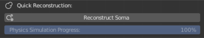
Note that if any of these parameters are changed later, the user must re-click on this button to apply the changes.
Rendering the soma mesh requires some work to setup the lighting and camera and locate them properly in the scene. NeuroMorphoVis automates the process with a single click in the GUI.
Users must set the following option in the configuration file to render a still image of the reconstructed soma:
## Render a static frame of the final reconstructed soma mesh only.
# Use ['yes' or 'no'], by default 'no'.
RENDER_SOMA_MESH=yesThis parameter defines the resolution of the rendered image of the soma mesh. This image have the same resolution in width and height and that's why the Frame Resolution slider has only a single value.
Range: 512 - 10240
Default Value: 1024
This option can be set in the configuration file as follows:
# The resolution of close up images or somata images.
CLOSE_UP_FRAME_RESOLUTION=1024Normally, the extent of the reconstructed soma mesh cannot exceed 20-30 microns. However, users can control the dimensions of the view in case a close up on a given part of the soma mesh is wanted.
Range: 20 - 100
Default Value: 20
This option can be set in the configuration file as follows:
## Close up view dimensions (in microns)
# Acceptable range [20 - 100] microns
CLOSE_UP_VIEW_DIMENSIONS=25After setting all the rendering parameters, users can render a still image of the reconstructed soma using any of the following buttons:
- Front This button renders the front view of the soma.

- Side This button render the side view of the soma.

- Top This button renders the top view of the soma.

This option can be set in the configuration file as follows:
## Camera view
# Use [front] to render the front view (default).
# Use [side] to render the side view.
# Use [top] to render the top view.
# Use [all] to render all the views.
CAMERA_VIEW=frontUsers can also render animated sequences of the reconstructed soma mesh and analyze it from all the views. NeuroMorphoVis supports two types of animations: 360 and progressive sequences.
The users can render a 360 sequence of the reconstructed soma mesh to verify its structure from all the views. This animation is created by clicking on the 360 button shown above. The sequence (a set of frames ordered from 00000.png to 00360.png) will be generated in a directory with the same name of the morphology in the sequences folder under the Output Directory that must be set in the Input / Output panel. For example, if the morphology file name is C031097B-I4.CNG.swc or C031097B-I4.CNG.h5, then the output directory will be named C031097B-I4.CNG_soma_mesh_360. After compositing the frames, this 360 movie is created.

This option can be set in the configuration file as follows:
# Render a 360 sequence of the reconstructed soma mesh, by default 'no'.
RENDER_SOMA_MESH_360=yesIf the Soft Body technique is used to build the soma, users can render the progressive reconstruction of the soma mesh to analyze the deformation and extrusion processes that occur to an initial ico sphere to yield the reconstructed soma mesh. This animation is created by clicking on the Progressive button shown above. The sequence (a set of frames ordered from 00000.png to 00100.png) will be generated in a directory with the same name of the morphology in the sequences folder under the Output Directory that must be set in the Input / Output panel. For example, if the morphology file name is C031097B-I4.CNG.swc or C031097B-I4.CNG.h5, then the output directory will be named C031097B-I4.CNG_soma_mesh_progressive. After compositing the frames, this progressive reconstruction movie is created.
This option can be set in the configuration file as follows:
# Render a sequence showing progressive soma reconstruction, by default 'no'.
RENDER_SOMA_MESH_PROGRESSIVE=yes
Note This option is only valid if the
SOMA_RECONSTRUCTION_METHOD=soft-body, otherwise it will be ignored.
Finally, the users can export the reconstructed surface mesh of the soma. The users can exploit the native support of Blender to export meshes into different file formats. But since we assumed that end users might not have any Blender experience, we have addedd four buttons to export the reconstructed soma meshes into the following common file formats:
-
Wavefront (.obj) The OBJ file format is a simple data-format that represents 3D geometry alone — namely, the position of each vertex, the UV position of each texture coordinate vertex, vertex normals, and the faces that make each polygon defined as a list of vertices, and texture vertices. Further details about this file format can be found here.
-
Stanford (.ply) PLY is a file format known as the Polygon File Format or the Stanford Triangle Format. It was principally designed to store three-dimensional data from 3D scanners. The data storage format supports a relatively simple description of a single object as a list of nominally flat polygons. A variety of properties can be stored, including: color and transparency, surface normals, texture coordinates and data confidence values. The format permits one to have different properties for the front and back of a polygon. Further details about this file format can be found here.
-
Stereolithography CAD (.stl) The STL file describes a raw, unstructured triangulated surface by the unit normal and vertices (ordered by the right-hand rule) of the triangles using a three-dimensional Cartesian coordinate system. Further details about this file format can be found here.
-
Blender Format (.blend) The exported file can be opened only in Blender and can be used for rendereing purposes.
This export options can be set in the configuration file as follows:
# Export soma .PLY mesh, by default 'no'.
EXPORT_SOMA_MESH_PLY=yes

# Save soma .OBJ mesh, by default 'no'.
EXPORT_SOMA_MESH_OBJ=yes

# Save soma .STL mesh, by default 'no'.
EXPORT_SOMA_MESH_STL=yes

# Save soma .BLEND mesh, by default 'no'.
EXPORT_SOMA_MESH_BLEND=yes-
Luengo-Sanchez, S., et al. A univocal definition of the neuronal soma morphology using Gaussian mixture models. Frontiers in neuroanatomy, 9, 137, (2015).
-
Abdellah, Marwan, et al. "NeuroMorphoVis: a collaborative framework for analysis and visualization of neuronal morphology skeletons reconstructed from microscopy stacks." Bioinformatics 34.13 (2018): i574-i582.
-
Abdellah, Marwan, et al. "Reconstruction and visualization of large-scale volumetric models of neocortical circuits for physically-plausible in silico optical studies." BMC bioinformatics 18.10 (2017): 402.
-
Brito, Juan, et al. "Neuronize: a tool for building realistic neuronal cell morphologies." Frontiers in neuroanatomy 7 (2013): 15.
-
Lasserre, Sebastien, et al. "A neuron membrane mesh representation for visualization of electrophysiological simulations." IEEE Transactions on Visualization and Computer Graphics 18.2 (2012): 214-227.
-
Starting
-
Panels
-
Other Links
![]()
![]()