Skip to content

Import options

Sven edited this page Jul 23, 2020 · 1 revision

Import options

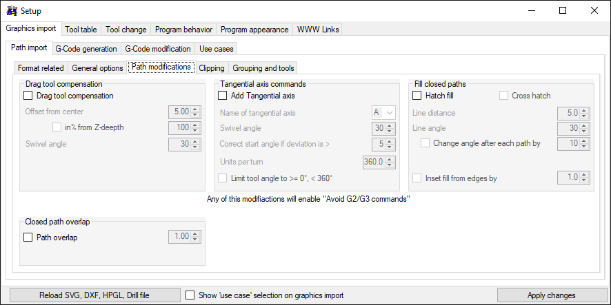
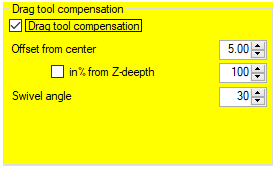
Note: some settings will change the expected result a lot, these settings are marked with a yellow background when activated.

Format related
General options
Path modifications
Clipping
Grouping and Tools
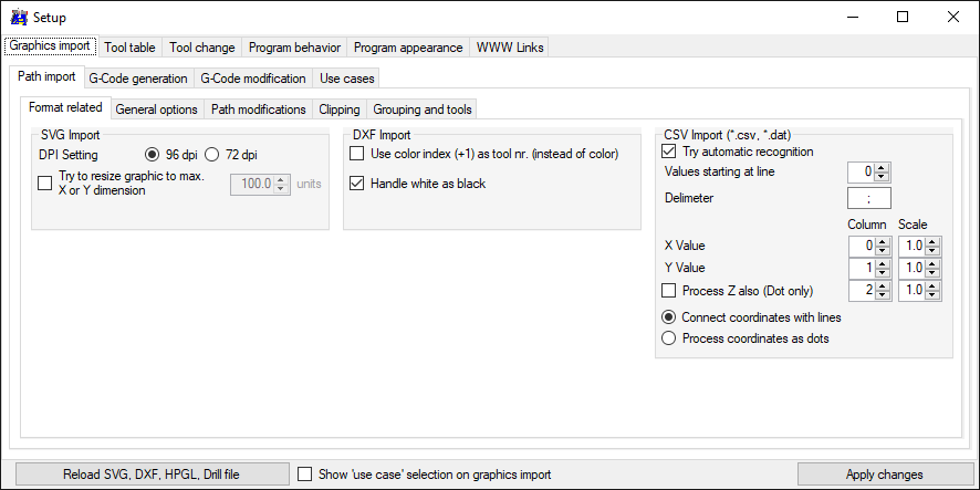

Format related options

Setup some graphic-format related options


SVG

  • 'DPI setting' - the internal resolution of the drawings (inkscape uses 72 dpi in older version), 96 dpi is the actual CSS defined value.
  • 'Try to resize graphic to an given value' - to avoid the need of later scaling to fill your drawing area.

DXF

  • 'Use color index +1' - the colors inside DXF are defined via a color-table (0=black, 1=red, 2=yellow, 3=green...), this index can be used to select tools.
  • 'Handle white as black' - in LibreCAD the default drawing color is white - not so optimal for a plotter.

CSV Import

  • 'Try automatic recognition' - a line at the end of the CSV-file will be analyzed for delimeter, amount of columns, resulting start line etc.

Top


General Options

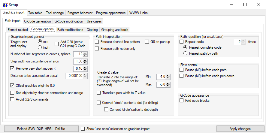
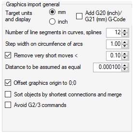
Graphics import general

  • 'Target units' - import and 2D-view will be set to 'mm' or 'inch' ('inch' is not fully tested)
  • 'Number of line segments' - as higher the number as less angular the curve will be
  • 'Remove very short moves' - short moves can be eleminated to reduce code size and speed-up process time
  • 'Distance to be assumed as equal' - little gaps in drawings will be closed and prevent unneeded pen-up/down
  • 'Offset graphics to origin 0;0' - I found a lot of HPGL drawings with a huge offset, use this option to remove an offset during import
  • 'Sort objects by shortest connections and merge', example: 'unsorted' ' sorted'
  • 'Avoid G2/3 commands' - some graphic objects will be converted to G2/G3 G-Code, this option will prevent G2/3 commands. Some other options automatically enable this option.

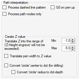
Path interpretation

  • 'Process dashed line pattern' - breaks a line with pen-up/down commands in the given pattern (SVG, DXF)
  • 'Translate pen width to Z value' - use a Z value other than 'Z-Height engrave', calculated from the pen width, used in the drawing (SVG, DXF)
  • 'Process path nodes only' - Instead of lines, dots will be created at the start- and end-point of a line (or center of a circle)

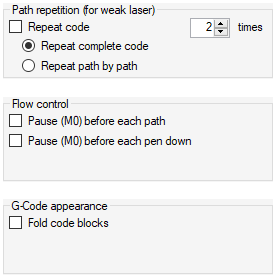
Path repitition

The complete graphic can be repeated, e.g. when using a weak laser:
  • whole graphic by whole graphic
  • single path by single path

Flow control

To change pen or tool, a pause can be inserted before starting a new path.

G-Code appearance

The resulting G-Code inside the editor can be folded.

Top


Path modifications

Intended for use with a knife or brush, to compensate the axis offset of the tool.

Click to watch video

Tangential axis commands

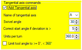
Intended to use with a tangential knife - a knife which is attached to a vertical extra axis.
With this option, all G-Code commands will be extended by a tangential axis command, which always points into the movement direction.
  • Select the axis name to be used as G-Code command
  • 'Swivel angle' defines when to lift the knife, adjust the angle and lower the knife - if the change in angle is too big.
  • 'Correct start angle' - a single tangential axis command will be set before a straight line, if the change in angle is bigger than this value.
  • 'Units per turn' - when using 'Z' as axis name, the feedrate for tangential axis is limited by the X and Y axis when together in motion. Using e.g. 3.6 units for a full turn, speeds up the tangential motion dramatically.
  • 'Limit tool angle >=0°, < 360°' prevents the tool to exceed this angle-range (e.g. because the angle of rotation is limited by cables).

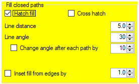
Fill closed paths

A hatch fill can be applied to closed paths.
  • 'Cross hatch' - create a scond line pattern, turned by 90°
  • 'Line distance' - distance between the hatch lines
  • 'Line angle' - angle of the hatch lines
  • 'Change angle after each path' - after each filled object, the 'line angle' will change by this angle
  • 'Inset fill from edges' - keep distance to the surrounding border

Closed path overlap

Intended to use with a laser-cutter. The closed path will be repeated for the given length.

Top


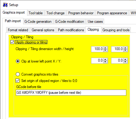
Clipping

Clipping and Tiling

  • 'Clipping / Tiling dimension' - set the size of the clipped graphic or tile
  • 'Clip at lower left point' - select clipping and set the start point for clipping
  • 'Convert graphics into tiles' - select tiling, to keep whole graphics information in several tiles
  • 'Set origin of clipped tiles to 0;0' - if off, the whole graphic looks unchanged, but selected tiles will be highlighted
  • 'G-Code before tile' - this code will be applied before the next tile-graphics information will be send. Some varaiable are available to control other axes:
    '#INDX' / '#INDY' - index of the following tile for X and Y axis
    '#OFFX' / '#OFFY' - offset of the following tile for X and Y axis in units
Note: Clipping and tiling enables 'Avoid G2/3 commands'. Tiling occupies the grouping option.

Top


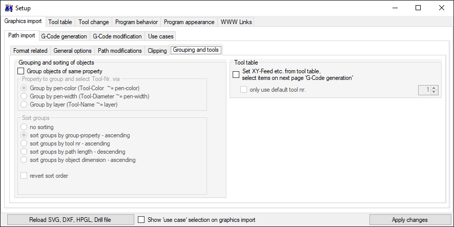
Grouping and Tools

Grouping and sort

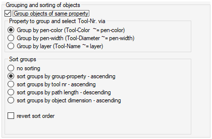
  • The graphic objects can be grouped by pen-color, pen-width or layer-name, e.g. to process them with different tools
  • The order of the groups can be sort by group-property (pen-color, pen-width, layer-name) or tool number (calculated from group-property), path-length or path-dimension
  • Note: if 'Tiling' is selected, grouping is occupied by the tile information.

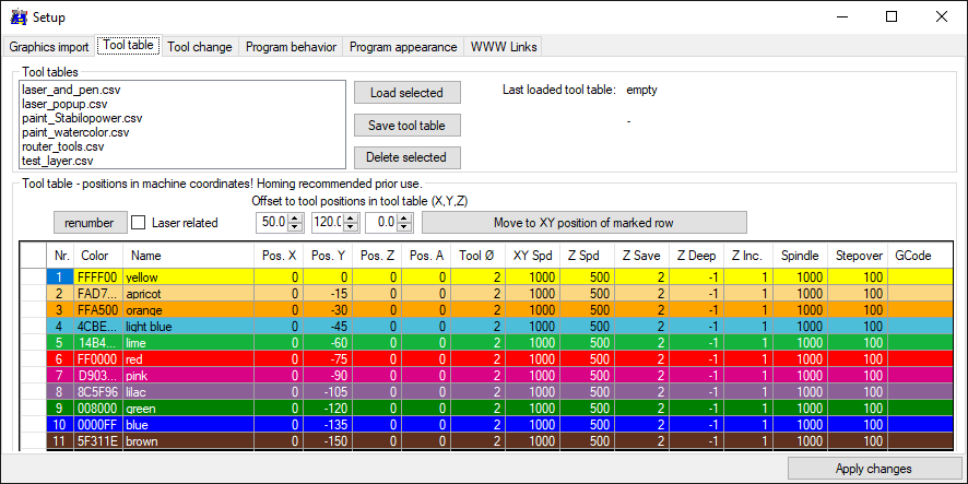
Tool table

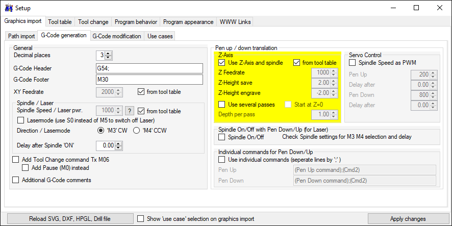
With this option, following settings can be get from the tool table, instead from the setup-tab: XY-Feedrate, Spindle-speed (or Laser power), Z-axis settings (Z-Feedrate, Z-save, Z-engrave).
See setup pages below and note the 'from tool table' check boxes.


Top


Clone this wiki locally