-
-
Notifications
You must be signed in to change notification settings - Fork 295
Assemble laser cut parts
This page has moved! For the latest assembly instructions, see the v0.5 Assembly Instructions
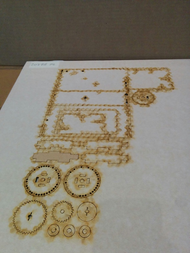
All of the parts will arrive as a single laser cut sheet:

Pop out all of the pieces.

Make sure you peel off the backing tape from all pieces for a cleaner outer surface and to make sure the pieces fit together with the right tolerances.
First put together the 4 spool struts which form the central structure of the spool.

Then slide the 2 spool disks onto either side of the spool struts.

Turn the spool on its end with the longer strut taps facing up and drop one bushing into the center of the strut tabs:

Then slide the spool gear onto the end, followed by another bushing:

The final remaining bushing fits into the other side of the spool. Set the spool aside for now (don't worry about the flaps - they'll be attached at the very end).
The driving gear comes from two pieces: the gear itself and a bushing, each of which is keyed to press-fit onto the double-slotted shaft of the 28BYJ-48 motor. To align these when gluing them together, cut a small rectangle of a spare PVC card that's 10mm wide and insert it into the notch:

Then lightly apply wood glue to one side of the bushing.

Finally, slide the bushing onto the card and clamp the pieces together until the glue dries.

The enclosure consists of 5 pieces:
- Bottom - has the laser-etched label, with 3 and 5 protruding tabs on the right and left sides, respectively.
- Top - the smallest enclosure piece, with 3 protruding tabs on either side.
- Left - the larger of the two sides, with holes for the 5mm spool rod, idler gear bolt, and motor mount.
- Right - the smaller of the two sides.
- Front - mostly consists of the large rectangular viewing window.
Before assembling the enclosure, attach the motor and idler gear to the left side. The idler gear is mounted using an M4 bolt, with a nut on either side of the MDF panel to hold the bolt in place while allowing the idler to spin freely.

All of the enclosure pieces attach to one another using captive-nut joints.

Leave the front for last so that you can hold the spool in place while inserting the 5mm rod.

In order to stop the bottom flaps from swinging back and forth and instead sit firmly in place after flipping down, we use a bolt as a backstop. This also helps the flaps make a louder sound when they flip down against the lower flaps.
As a precaution to avoid scratching the flaps, first take some heatshrink tubing and form it to the bolt's threads:

Once heated the tubing should fit tightly around the threads and provide a smooth surface for the flaps to slide against:

Allow the tubing to cool, and unscrew it from the bolt. Place the bolt in the lower slot in the left side of the enclosure (the shorter side) facing inward, and secure it in place with a nut. Then screw the formed heatshrink tubing back onto the end of the bolt to cover the exposed threads. You can loosen and slide the bolt forward or backward to the appropriate position.

Continue to Build a flap-cutting jig