- V1 - only counter for two channels. Moved to separate thread and is no longer supported.
- V2 - meter for two channels + two leak sensors.
- The firmware is the same in both versions.
- Designed for two water meters and two leak detectors.
- Does not work with namur system and meters with hall sensor. Only short-circuit/open-circuit, e.g. reed switch.
- Keeps count of closures-openings, increasing the number of liters each time by the set value from 1 to 10 liters (default is 10 liters per pulse).
- Sends an On command when a leak is detected on any sensor to two actuators at once.
- Saves readings in the module's non-volatile memory.
- Transmits readings via Zigbee network.
- EndPoints with On_Off clusters have the ability to connect directly to the actuator without the coordinator.
- Interfacing with smart homes via zigbee2mqtt.
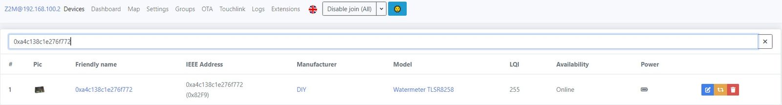
- Initial configuration is done via the zigbee2mqtt web interface.
- Connect to zigbee network - press the button 5 times.
- Leave the zigbee network - press the button 5 times.
- Restart the module - press the button for more than 5 seconds (this is just a reset, without changing any settings).
- If the button is pressed once, the module wakes up and sends a report.
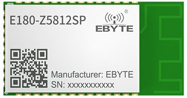
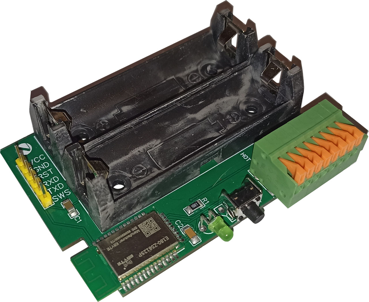
The project uses a module from E-BYTE on the TLSR8258F512ET32 chip, the E180-Z5812SP.
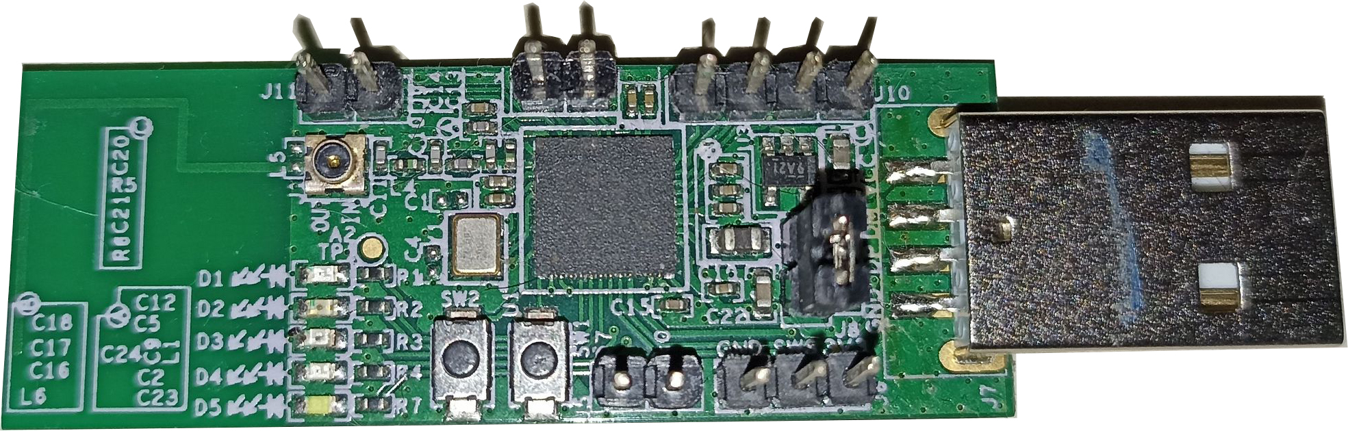
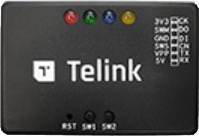
Everything was tested on this dongle from Telink
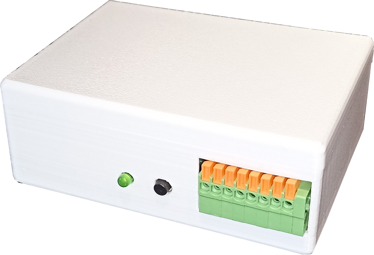
The case is made on a 3D printer.

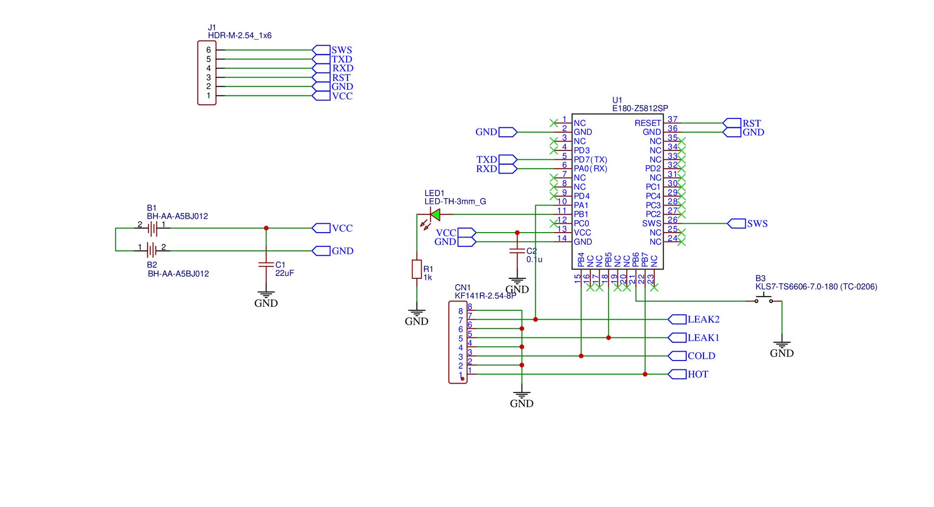
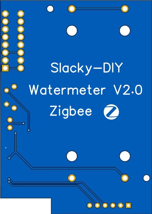
Module Schematic.
The leakage sensor itself consists of two contacts. When the contacts are immersed in water, the resistance between them changes. This is what the device detects.
It is possible to buy ready-made ones, for example from the company Gidrolock - Gidrolock WSP.
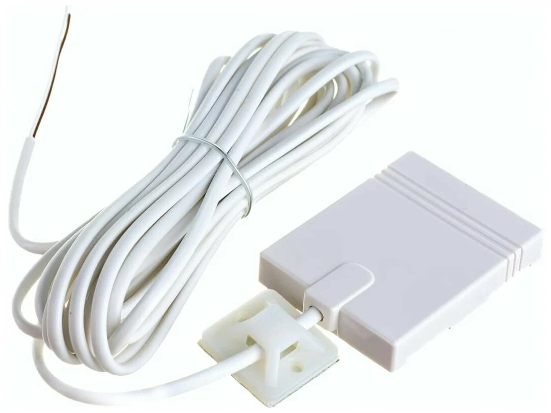
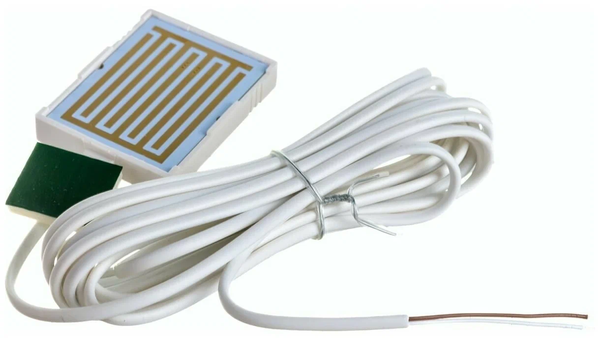
Or on Aliexpress these
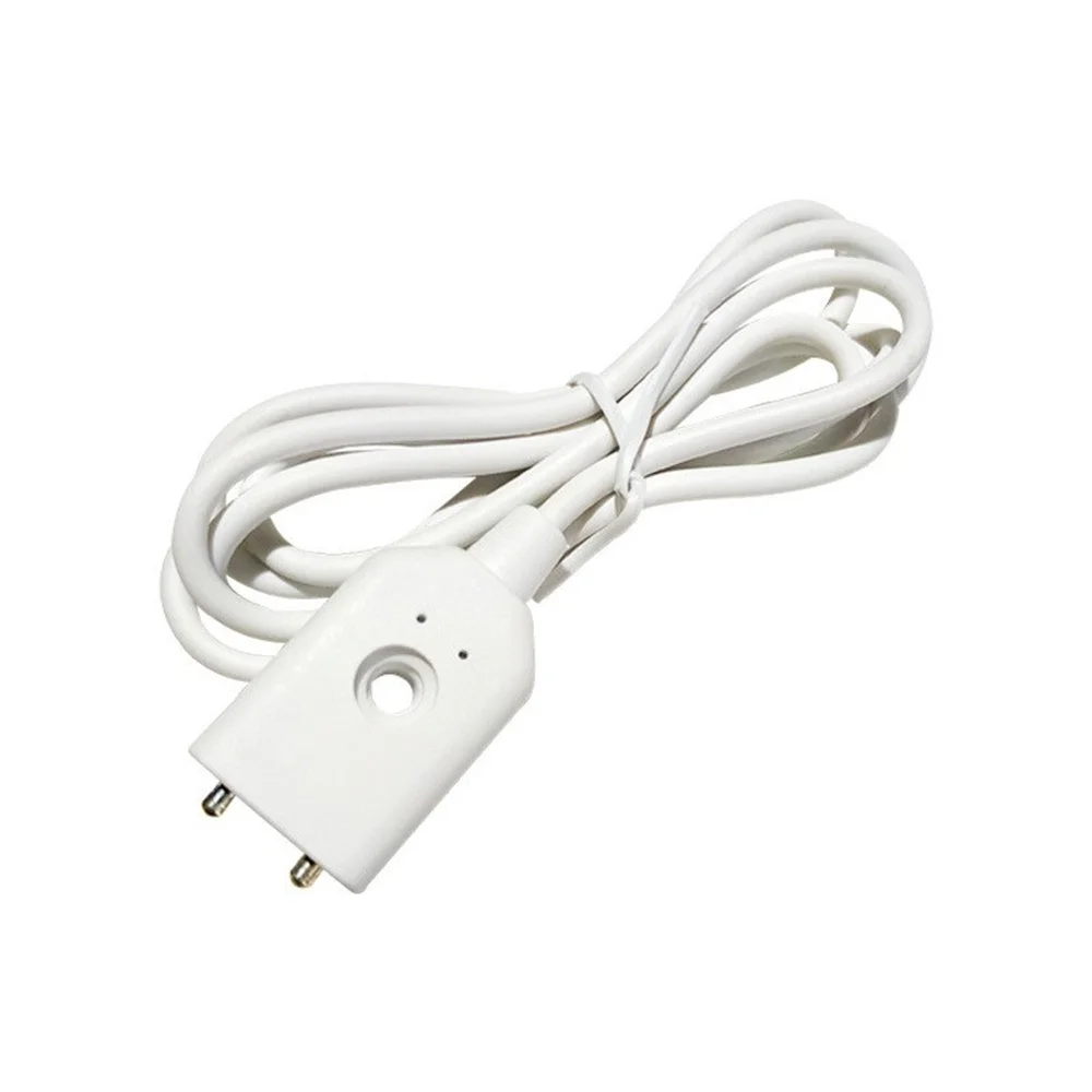
Or solder two wires to two pins of, for example, a pin header connector. The result will be the same :)

The latest firmware must be injected into the module using github.com/pvvx/TLSRPGM or the original Telink programmer.
You can read here how to make an inexpensive programmer based on TB-03 or TB-04 modules.
The project is shaped in such a way that it can be built with regular make on Windows, in the Git Bash shell, as well as on Linux (I tested on Debian 11).
You can read how to add a project to Eclipse here. Everything is exactly the same, but for a different project.
The firmware is built according to the schematic, i.e. the board file board_8258_diy.h is connected. The dongle board is also adapted, i.e. board_8258_dongle.h. For other variants you will have to edit the file of the required board yourself.
At the first startup, an attempt is made to connect to the Zigbee network. If the attempt is successful, the module enters the normal operating mode.
Polling For the first 30 seconds, the module wakes up every 3 seconds. After 30 seconds, the module goes to sleep for 5 minutes. After 5 minutes, it wakes up again once every 3 seconds for the next 30 seconds. Then it goes back to sleep for 5 minutes. And so on in a circle. You could make the module wake up once every 5 minutes, but zigbee2mqtt by default checks for devices on the network about once every 10 minutes. And it starts swearing in the log that the device is not found and sets the status offline. With such an uneven scheme this problem is eliminated. This of course can be configured in zigbee2mqtt, but I preferred this option. Making the wake-up period always once every 3 seconds is an unreasonable waste of battery life.
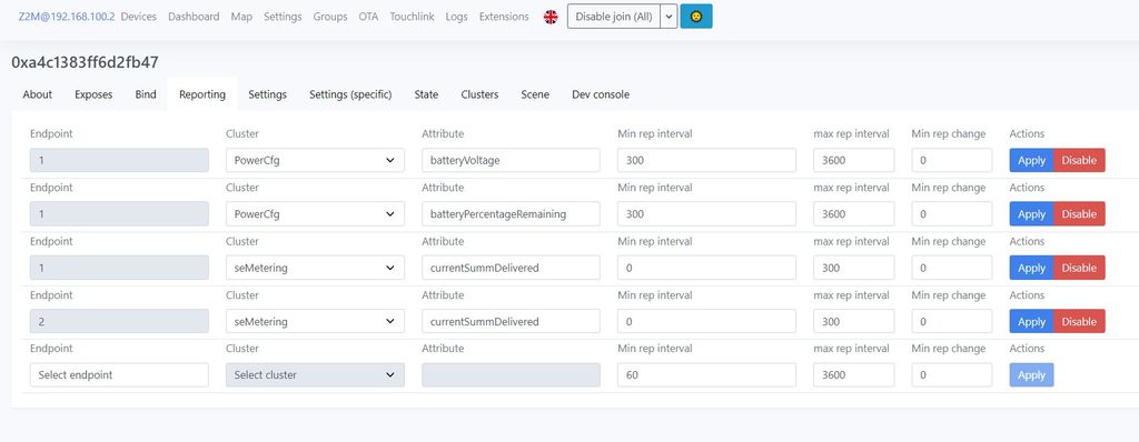
Reporting
The module sends four different reports. Two for the battery and two more for the cold and hot water meter. They have different sending periods.
The module checks the battery voltage once every 15 minutes. Reports on battery status (voltage in mV and remaining life in %) are sent not earlier than 5 minutes from the previous one (if there were changes), but not later than 1 hour (even if there were no changes).
The report of the water meter value is sent immediately when the value increases. And no later than 5 minutes from the previous report. If 5 minutes seems too frequent to someone, this can always be corrected via the zigbee2mqtt web interface in the Reporting section.
Reports are also forcibly sent within 5 seconds by pressing the instrument button.
The code used in Telink's examples for reporting is a bit (I would even say a lot!) crooked. It prevents the module from falling asleep for more than 1 second. And if it is not critical for devices that are powered from stationary sources, it is already a disaster for battery-powered devices. That's why the original reporting aglorithm was replaced by a custom one, which is based on starting timers by MinInterval and MaxInterval, which allowed the module to fall asleep exactly for these intervals, and not for 1 second, as it was before.
LED indication of module modes
If the module does not blink the LED for a long time (more than 5 minutes), it is in the deep sleep mode. The module can exit this mode in two cases. First - if the user presses the button. The second - if the reed switch in any water meter is triggered (closed or open).
- The LED flashes at intervals of 5 seconds to 5 minutes - the module is online and operating in normal mode.
- LED blinks with two flashes at intervals of 5 seconds - OTA firmware update is in progress.
- LED blinks with three flashes at intervals of 5 seconds to 5 minutes - the module is not online - it has not been plugged in, e.g. the batteries have been inserted into the device, but there is no zigbee network or the connection ban is activated; or it has been plugged in, but there are some network problems at the moment. In any case, the module will work in this mode for about 30 minutes. If it fails to connect to the network or restore communication during this time, it will go into a deep sleep. In this mode, in order to contact the module, you must wake it up by pressing the device button.
Module memory and where the config is stored
According to the TLSR8258F512ET32 chip specification, the memory is distributed as follows
0x00000 Old Firmware bin 0x34000 NV_1 0x40000 OTA New bin storage Area 0x76000 MAC address 0x77000 C_Cfg_Info 0x78000 U_Cfg_Info 0x7A000 NV_2 0x80000 End Flash
It turns out that the firmware can't be bigger than 0x34000 (which is actually confirmed by checking the SDK to determine the size of the uploaded file when updating OTA), but when using the firmware from address 0x40000, you can see that 0x36000, not 0x34000, is allocated for it. It appears that 0x2000 is never used. This is what we will use to store the intermediate config. The intermediate config is written to NV_2 (somewhere in the area from 0x7a000 to 0x7c000). The NV_MODULE_APP module with the number NV_ITEM_APP_USER_CFG is used (for understanding see app_cfg.h and sdk/proj/drivers/drv_nv.h).
After the hardware firmware is injected into the module, it always starts from address 0x00000. After OTA update, the start address changes. If before the update it was 0x00000, after the update it becomes 0x40000. If before the update it was 0x40000, after it becomes 0x00000. And so on in a circle after each OTA update.
At the moment of module startup we check whether the firmware is loaded from address 0x00000 or 0x40000. If it is loaded from address 0x00000, we use the area from 0x40000 to 0x74000 to store the config. If the firmware is loaded from address 0x40000, we use the area from 0x00000 to 0x34000 to store the config.
Examples of device log output after OTA update
- Updated for the first time
OTA update successful. OTA mode enabled. MCU boot from address: 0x40000 Save restored config to nv_ram in module NV_MODULE_APP (6) item NV_ITEM_APP_USER_CFG (45)
- Updated a second time
OTA update successful. OTA mode enabled. MCU boot from address: 0x0 Save restored config to nv_ram in module NV_MODULE_APP (6) item NV_ITEM_APP_USER_CFG (45)
The config is written to the selected area each time the water meter is triggered in 0x100 increments. I.e. the first time the config is written to address 0x40000 (0x00000), the second time 0x40100 (0x00100), the third time - 0x40200 (0x00200) and so on until it reaches the boundary 0x74000 (0x34000). And then it starts writing again from the initial address 0x40000 (0x00000).
- Output device log when writing config from address 0x0
Save config to flash address - 0x0 cold counter - 2010 Save config to flash address - 0x100 cold counter - 2020 Save config to flash address - 0x200 cold counter - 2030 Save config to flash address - 0x300 cold counter - 2040 Save config to flash address - 0x400
- Output device log when writing config from address 0x40000
Save config to flash address - 0x40000 cold counter - 2090 Save config to flash address - 0x40100 cold counter - 2100 Save config to flash address - 0x40200 cold counter - 2110 Save config to flash address - 0x40300 cold counter - 2120 Save config to flash address - 0x40400 At the moment of OTA update the config is saved in nv_ram. It will remain there until the OTA update is successfully completed.
After successful completion of the OTA update, the module reboots, reads the config from nv_ram, checks at which address the config should be written in normal mode and saves it at address 0x00000 or 0x40000. And so on until the next update.
Leak detectors
When a leak is detected (i.e. the contacts of any leak sensor are immersed in water), the state of the IAS cluster changes and two On commands are sent immediately to the On_Off clusters at Endpoints 4 and 5. When the water dries, the state of the IAS cluster changes and no commands are sent to the On_Off cluster.
Both On_Off clusters should directly "bind" to the executable (enforced in the zigbee2mqtt web-interface in the bind device section). What it gives. Even if the network goes down, when for example the coordinator is not working, Watermeter will still send the selected On (off or toggle) command directly to the actuator and everything will work (we understand that the actuator must have a duplicate autonomous power supply!). Binding both channels to the same device is not recommended.
Zigbee Claster and Attribute
The firmware uses 5 endpoints, that's like 5 different logical devices on one physical device. What for. The Zigbee standard does not allow using the same clusters with the same attributes on the same endpoint. And we have two identical counters with the same CurrentSummationDelivered attributes in the SeMetering cluster. And two identical On_Off clusters. So the first enpoint has the hot water meter, the second has the cold water meter, the third has the settings, the fourth has the IAS and the first On_Off, and the fifth has the second On_Off.
- WATERMETER_ENDPOINT1 contains all the base clusters required for zigbee operation, as well as the SeMetering cluster (the first counter)
- WATERMETER_ENDPOINT2 contains the second SeMetering cluster (second counter)
- WATERMETER_ENDPOINT3 contains the third SeMetering cluster - custom attributes (which are not in the zcl specification) are used here for initial meter configuration.
- WATERMETER_ENDPOINT4 contains an IAS cluster for reporting a leak and an ON_OFF cluster for sending a command to the first water tap actuator (e.g. hot water).
- WATERMETER_ENDPOINT5 contains another ON_OFF cluster for sending a command to a second water tap actuator (e.g. cold water).
In principle WATERMETER_ENDPOINT3 could have been left out and everything put into WATERMETER_ENDPOINT2, but it was done this way.
Open the file configuration.yaml from zigbee2mqtt for editing. And add to the end of the file
external_converters:
- watermeter_wleak.js
ota:
zigbee_ota_override_index_location: local_ota_index.json
Copy the files
watermeter_wleak.jsandlocal_ota_index.jsonfrom project folder to the same place whereconfiguration.yamlfrom zigbee2mqtt is located. Don't forget to allow connection of new devices -permit_join: true. Reboot zigbee2mqtt. Check its log that it has started and is working normally.
Next, insert the batteries into the device. If the power has already been supplied, press the button 5 times in a row. The device should connect to the zigbee network. If the connection was successful, we will find our device in zigbee2mqtt.
Once the device is connected to the network and zigbee2mqtt has detected it, you can start setting the initial values of the meters. Three custom attributes have been created in the Smart Energy cluster to configure the initial values. These are setting initial values for hot water, cold water and how many liters to add per pulse (different meters can add from 1 liter to 10 liters per pulse, see the specification of your meter).
Go to the zigbee2mqtt web-interface and go to the exposes section. Set the initial values.
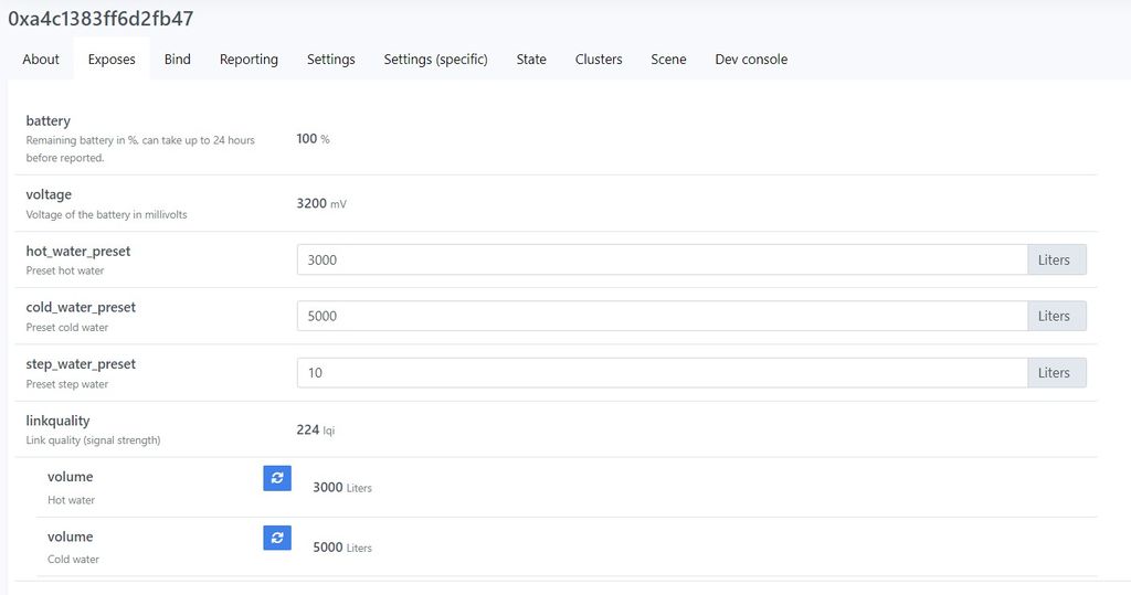
Then press the button on the device so that it wakes up and accepts the data. After that it is better not to go into this section anymore, because if you click on some setting field, zigbee2mqtt will immediately send the value that is marked there. Unfortunately I haven't found how to do it via the confirmation button in the web-interface.
Leak detectors
Go to the exposes section of the watermeter device.
Select which commands to send when a leak is detected.
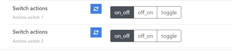
- If on_off is selected, the unit will send an off command when a leak is detected.
- If off_on is selected, the unit will send an on command when a leak is detected.
- If toggle is selected, the unit will send a toggle command when a leak is detected.
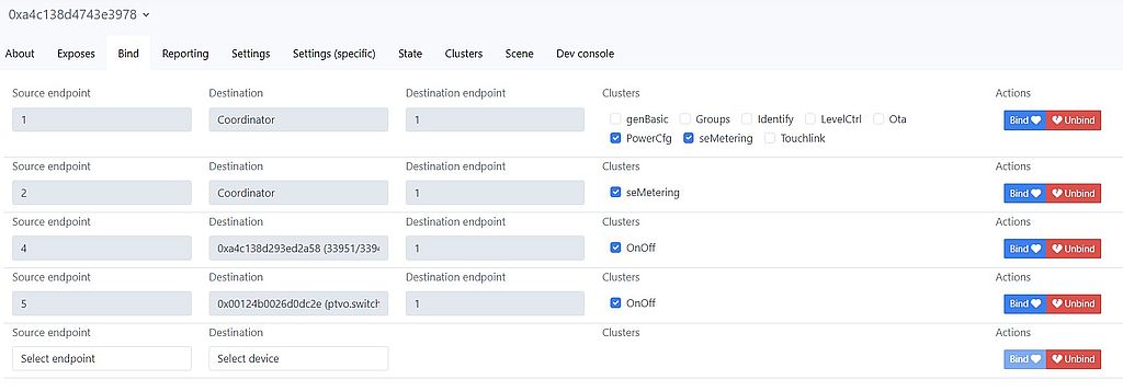
Next, go to the bind section.
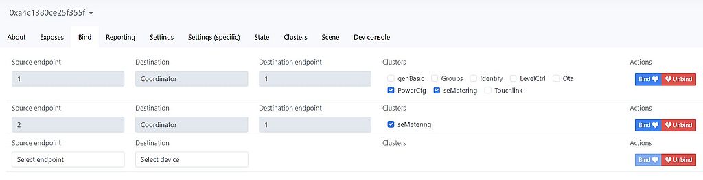
And add new "bindings" for endpoint 4 and endpoint 5.
Before using in real mode, you need to give a couple of "false" leaks, i.e. short the leak sensors one by one and make sure everything works!!!!
Also, only God can give a 100% guarantee, remember that :)))
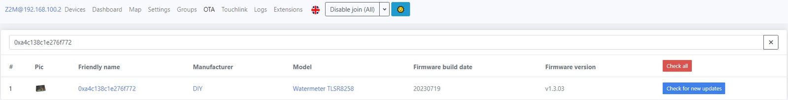
There is no automatic update in zigbee2mqtt for devices added through the converter. So if a new version is out, download the updated firmware file for OTA update, for example 656565-0204-13043001-watermeter_zed.zigbee . Rename it to simply watermeter_zed.zigbee and put it in the relative path zigbee2mgtt/images . Reboot zigbee2mqtt. Go to the OTA tab. And click on Check for new updates
If the update is accepted, the Check for new updates button will turn red with Update device firmware.
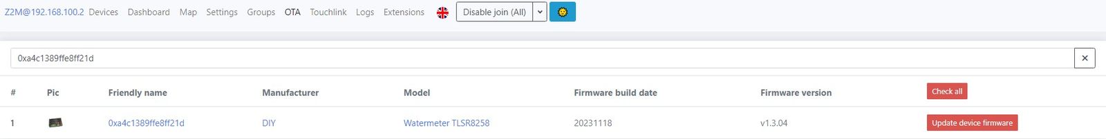
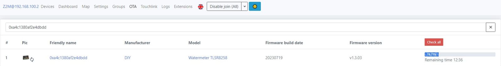
Click it and the update will start downloading (zigbee updates take a long time, something in the neighborhood of 20 minutes).
If the update fails, the update button will become red again and must be pressed again to wake up the module by pressing the button. The update process will be reset and will start from the beginning.
SDK doesn't have a check for low battery before loading the image. So I had to write my own implementation. The device will return an error to the coordinator - Aborted by device , if the battery charge is less than 50%, and the image file will not be loaded.

And lastly, so that the device will not be updated with some firmware with MANUFACTURER_CODE from Telink (for example, the device number will match), MANUFACTURER_CODE is replaced with custom one.
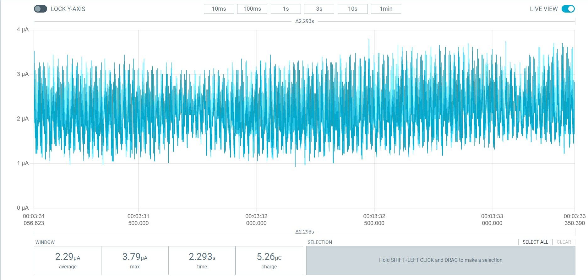
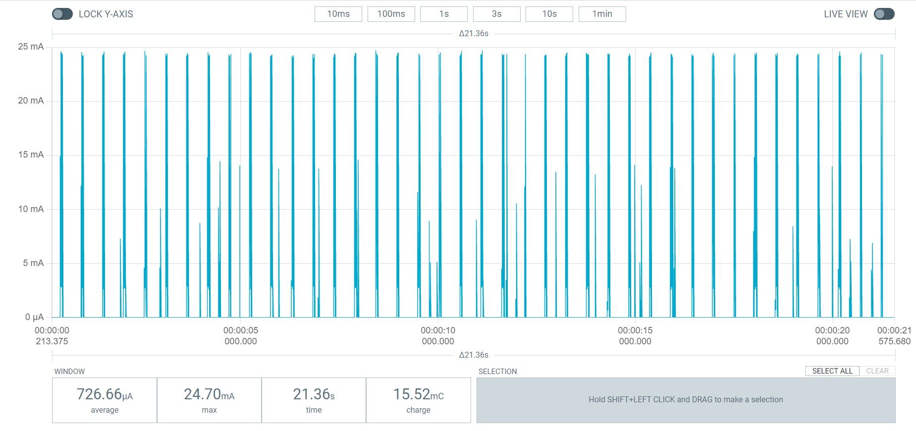
Long tests in real work have not been carried out yet. With ppk2 we measured consumption in different modes.
**The device is off-line, without power. When power is applied, it struts and connects to the mains.
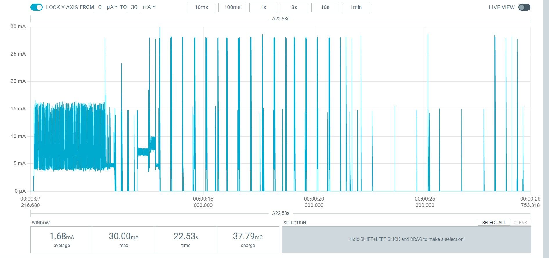
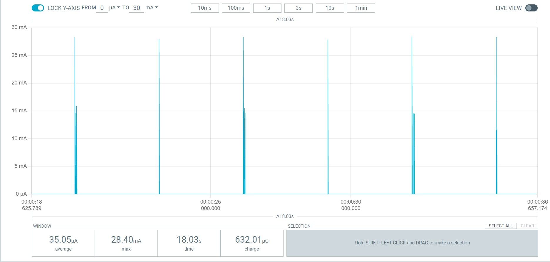
The device operates in normal mode with a POLL RATE of 3 seconds.
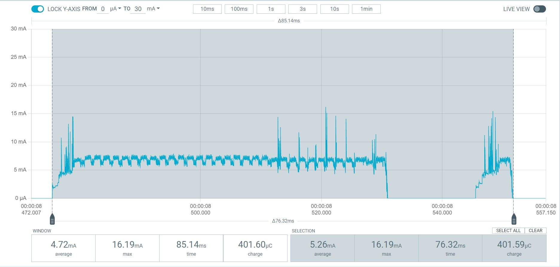
**The reed switch on the water meter is shorted out.
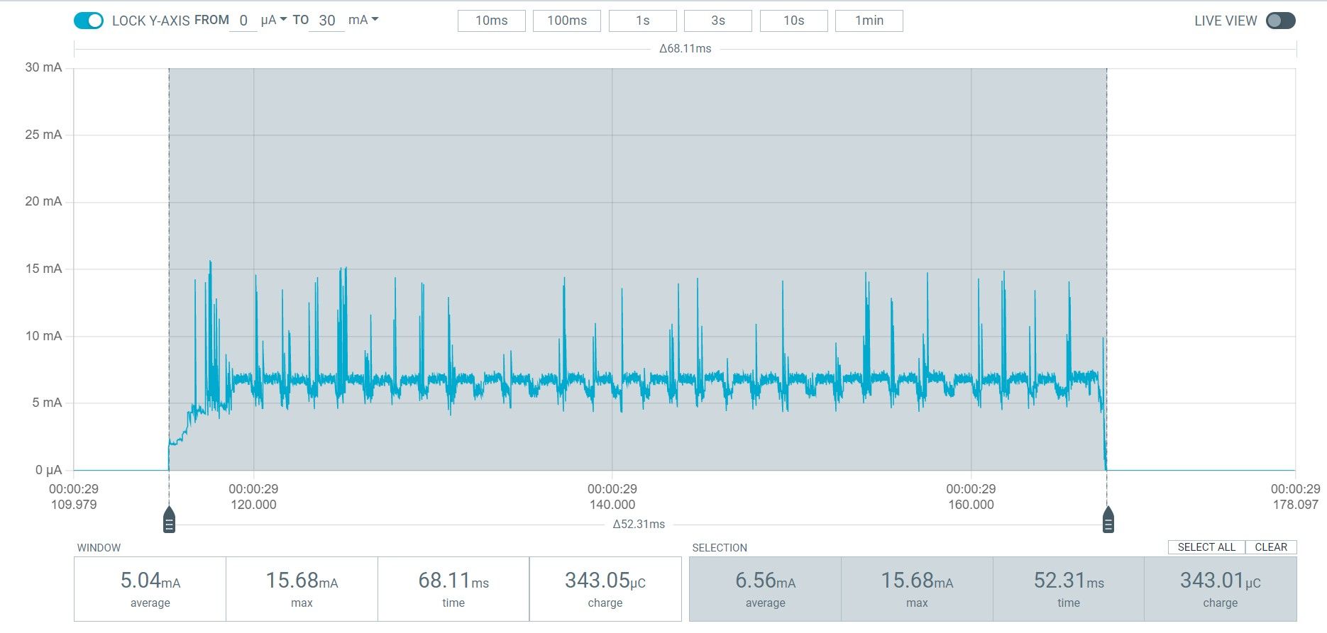
**The reed switch on the water meter is broken.
Start the module, which is already connected to the network and run it for 6 minutes without triggering the counters.
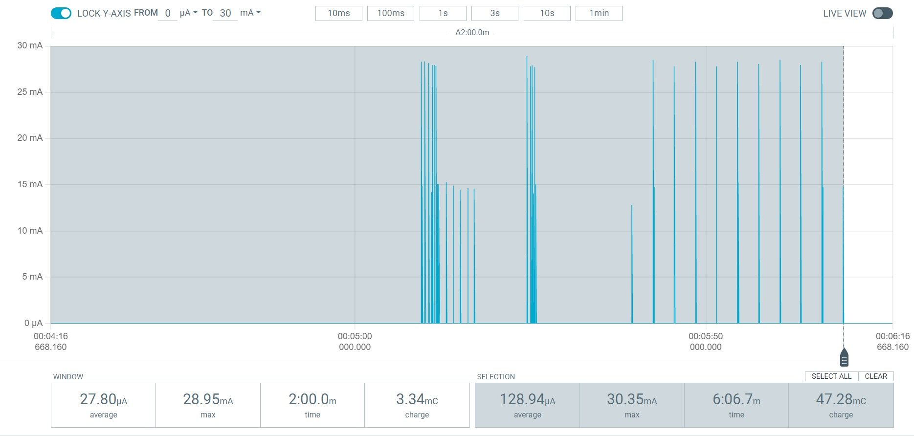
Module's sleeping.
OTA update.
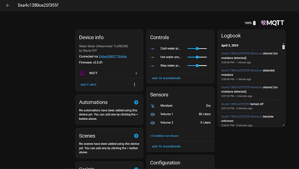
In Home Assistant, the meter will look like this.
Next, customize the counters if needed.
Cost of major parts as of February 2024 in Russia.
- Board 10 pcs. - 1500 p. (Aliexpress)
- Module E-BYTE E180-Z5812SP - 300 p. (Aliexpress)
- Battery Holder AA - 42 p. x 2 (Aliexpress)
- Terminal block - 49 p. (Aliexpress)
- Button - 3 p. (Aliexpress)
- LED - 12 p. (Chipdip)
- A pair of capacitors and resistance - 200 p.
Make LED indication of module operation modes.Done.Do DEEP SLEEP if the module is offline for more than 30 minutes.Done.Do an OTA reset if the update ended in an error so that it doesn't depend on user actions.Done.Add two channels for 2 leak sensors.Done.
- 1.0 - Beginning.
- 1.1 - Firmware without OTA.
- 1.2 - Added OTA update option.
- 1.3.01 - Changed version numbering. Added LED indication of module modes; deep sleep if not online for more than 30 minutes; OTA reset, if the update failed, the update will start from the beginning, done not to lose the main config.
- 1.3.02 - Changed the address for writing intermediate config during OTA. Previously it was written at address 0x74000, now it is written in nv_ram in NV_MODULE_APP module with number NV_ITEM_APP_USER_CFG (see app_cfg.h).
- 1.3.03 - Fixed a small glitch with reporting.
- 1.3.04 - Changed MANUFACTURER_CODE to custom. Added low battery check during OTA update.
- 1.3.05 - Fixed factory reset issue.
- 1.3.06 - Added ability to read custom attributes (needed for HOMEd).
- 1.3.07 - Fixed a bug with reading the custom attribute ZCL_ATTRID_CUSTOM_WATER_STEP_PRESET.
- 2.0.01 - Added two leak sensors. Changed the board and housing.
- 2.0.02 - Fixed a bug with reporting when maxInterval is 0.
- 2.0.03 - Added configuration of OnOff commands. The device can now send on, off or toggle when a leak is detected. Updated converter for zigbee2mqtt.
- 2.0.04 - SDK updated to version V3.7.1.2(PR).