In this example, we demonstrate how to model power electronics devices that perform current control using MathWorks products, focusing on:
- Simulation solver settings
- PWM generation modeling
- ADC modeling
The modeling style introduced in this example is not a universal solution applicable to all circuits. However, since this example uses the most basic half-bridge circuit in a Buck Converter, it has the potential to be applied to many power electronics circuits.
本例題ではシミュレーション速度と精度のバランスを取ることを目指したモデリングスタイルをお示しします。 電流制御を行うパワーエレクトロニクス機器をMathWorks製品を使ってモデリングした場合を題材に、
- シミュレーションソルバ設定
- PWM生成部のモデリング
- ADC部のモデリング
についてどのようにモデリングすべきかについて例を示しています。
本例題で紹介しているモデリングスタイルは、あらゆる回路において適応できる万能な例題ではありませんが、 本例題では最も基本的なハーフブリッジ回路を用いたBuck Converterを例題にしておりますので、多くのパワーエレクトロニクス回路に応用できる可能性があります。
If you want know more detale infomation "The techniq define Fast Simulation for Power Electronics Systems",Please Check this repo. 「パワー エレクトロニクス システムの高速シミュレーションを定義する手法」の詳細情報が必要な場合は、このリポジトリを確認してください。 https://github.com/simscape/FastElectricalSimulations
| Branch | Version |
|---|---|
| main | R2025b |
| R2021a | R2021a |
A branch saved in R2021a is also provided to allow customers who cannot use the latest version to try it out. Customers using versions earlier than R2025b but no earlier than R2021a are encouraged to use the R2021a branch.
最新バージョンを利用できないお客様にも触れていただくことを狙って、R2021aでのバージョンで保存したブランチも用意されています。 R2025b以前かつR2021a以降のバージョンをご利用のお客様はR2021aブランチをお試し下さい。
Japanese,English The ReadMe is available in both Japanese and English, but the internal annotations of the model are only in Japanese.
The primary method of supplying electricity has been a one-way flow from power plants to consumers. However, there is a growing demand for systems that allow for "bidirectional electricity supply" to achieve clean and sustainable energy systems.
To address this need, there is an increasing demand for power electronics equipment that can control current in both directions.
Specifically, there is a focus on:
- Bidirectional DC-DC converters
- Inverter output current control for motor applications
- Output current control for UPS and grid-tied inverters
The design requirements for these power electronics devices, which perform current control, need to be matched with the upstream system's requirements for bidirectional power supply to ensure efficient and appropriate design.
As a solution to these challenges, model-based design, which uses simulations to verify the operation of systems and power electronics devices and concretizes requirements in the early stages of design, is gaining attention.
2000年代初頭から、発電所から需要家までの単方向で電力を供給することが主流であった電力系システムですが、クリーンで持続可能なエネルギーシステム達成のために、"双方向に電力を供給するシステム"へのニーズが高まっています。
このようなニーズに対応するために、 システムで利用されるパワーエレクトロニクス機器において 双方向に電流を制御することに対する需要が高まっています。
具体的には特に、
- 双方向DCDCコンバータ
- モータ制御用途のインバータ出力電流制御
- UPS、系統連系インバータの出力電流制御
といった電流制御を行うパワーエレクトロニクス機器の設計要件を、 上流の"双方向に電力を供給するシステム"の要求と突き合わせて、妥当な設計を効率的に行うことが求められています。
そのような課題に対する手段として、 シミュレーションを用いてシステムやパワーエレクトロニクス機器の動作を確認し、設計の早期段階で要件を具体化するための開発手法である モデルベースデザインが注目されています。
This modeling style aims to balance simulation accuracy and speed, and we hope you find this demo useful for modeling power electronics devices in your research and development.
本例題では、可能な限りシミュレーション精度とシミュレーション速度を両立することを目指したモデリングスタイルでありますのでこのデモを参考に皆様が研究・開発で扱われているパワーエレクトロニクス機器をモデリングいただければ幸いです。

==
- Open the Project file in this repository and open one of the models saved in the Models folder.
- Run the simulation and check the waveform in the data inspector. ==
- このリポイトリのProjectファイルを開いて、Modelsフォルダに保存されているモデルのいずれかを開きます。
- シミュレーションを実行してデータインスペクターで波形を確認します。
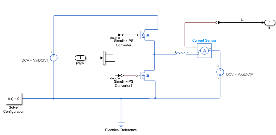
This model represents a bidirectional converter using a simple half-bridge circuit and achieves current control with a control model based on a simple PI controller. Comments explaining the modeling style and solver settings are written in Japanese and English within each subsystem hierarchy of the model file.
双方向のコンバータをシンプルなハーフブリッジで表現した回路モデルを制御対象とし、 シンプルなPIコントローラをベースとした制御モデルによって電流制御を実現しているモデルです。
モデリングスタイルやソルバの設定については、モデルファイル内の各サブシステム階層にわかれて 解説のコメントが日本語と英語で記述されています。


The BuckConverter_accuracy_oriented.slx model partially references an example model officially provided by MathWorks. In this sample, the power MOSFET library uses theNch-MOSFETBlock
In contrast, the BuckConverter_speed_oriented.slx model replaces the power MOSFET library with MOSFET(Ideal,Switching).
The Nch-MOSFET block provides a detailed switching device representation, including gate-voltage rise dynamics. This enables highly accurate and detailed switching behavior, but it also requires a shorter simulation step size, which can slow down simulation speed.
If the goal of the simulation is to verify the consistency of the circuit configuration, control structure, and control parameters, it is recommended to use ideal switching blocks such as MOSFET(Ideal,Switching) Although this simplifies the switching behavior, it still provides sufficient accuracy for tuning control parameters, allowing a better balance between simulation speed and accuracy.
In addition to the change in the power MOSFET library, the following modifications were also made to achieve a speed-oriented model:
- PWM generation section
- A/D conversion section
- Insertion of a Rate Transition block between the control model and the circuit model to explicitly specify execution rates These adjustments collectively result in a model optimized for simulation speed.
By running the CheckSimulationSpeed.m script, you can compare the execution times of the two models.
BuckConverter_accuracy_oriented.slxは下記の公開サンプルを参考に作成されています。 こちらのサンプルではパワーMOSFETライブラリに Nch-MOSFET ライブラリが利用されています。 https://jp.mathworks.com/help/sps/ug/buck-converter_example-ee_switching_power_supply.html
一方BuckConverter_speed_oriented.slxモデルは パワーMOSFETライブラリをMOSFET(Ideal,Switching)に変更しています。
Nch-MOSFETはゲート電圧の立ち上がりダイナミクスまで詳細に表現したスイッチングデバイスであるため、厳密で詳細度の高いスイッチング表現が可能ですがその分シミュレーションステップの刻み幅が短くなり、シミュレーション速度低下を招くことがあります。
シミュレーションの目的が回路構成と制御構成および制御パラメータの整合性確認であれば、パワー半導体はMOSFET(Ideal,Switching)に代表される '理想スイッチングライブラリ'ブロックを利用することをおすすめします。
これにより、スイッチングの挙動は簡略化されますが、 制御パラメータを調整するには十分な精度を得ることができるためシミュレーション速度と精度を両立性を高めることができます。
パワーMOSFETライブラリ以外にも、 ・PWM生成部 ・AD変換部 ・制御モデルと回路モデルの間にRate Transition Blockを挿入し、実行レートを明示的に指定する といった変更が加えられており、それにより速度を優先したモデルになっています。
CheckSimulationSpeed.m スクリプトを実行することで両者のモデルの実行時間を比較することができます。

2025-10-21_09-54-36.mp4
This is a full-bridge inverter modeling example assuming a single-phase grid-connected inverter. When generating a voltage output synchronized with the grid voltage, a PLL (Phase-Locked Loop) is normally used. However, since the objective of this example is to represent only the current control system, please note that this part has been simplified in the sample. No feedback loop is modeled to track variations in the grid voltage.
単相の系統連系インバータを想定したフルブリッジインバータモデリング例です。 系統電圧に同期する電圧出力を行う際は本来PLLを用います。 しかし、今回の例ではあくまで電流制御系のみを表現したかったのでこのサンプルではその部分が簡略化されている点には注意が必要です。 系統電圧の変動に追従するようなフィードバックループはモデリングされていません。
MATLAB®/ Simulink®/ Simscape™/ Simscape Electrical™/
Control System Toolbox™
モデルの伝達関数を表示するのに必要です。 It is needed to display the transfer function of the model.
[1]: Ricardo P. Aguilera et al. (2018). Digital Implementation of PI and Resonant Controller. In FREDE BLAABJERG(Eds.) CONTROL OF POWER ELECTRONIC CONVERTERS AND SYSTEMS volume1. Academic Press, pp.56-61
[2]: Dead-time Voltage Error Correction with Parallel Disturbance Observers for High Performance V/f Control http://itohserver01.nagaokaut.ac.jp/itohlab/paper/2007/IAS2007/hoshino.pdf
Copyright 2021 - 2025 The MathWorks, Inc.