Learn how to build your own Sigfox-connected device with a devkit and a couple of components
The goal of this repo is to learn how to build your own IoT device prototype using a Sigfox-connected devkit and a couple of components.
If you've read this repo before, some of this might feel like a déjà-vu. The idea is always to guide you from zero to a hundred. But, if you don't want to re-read something you already know, you can jump to this section.
-
A quick overview of what Sigfox is
a. The technology
b. Its limits and its advantages
c. The value chain -
Getting started
a. Devkits and firware
b. Sigfox Backend, Sigfox Cloud Platform, REST API and Callbacks
c. Using a platform to design your Data workflow
d. Making your device request a downlink -
Building your own prototype
a. Methodology
b. The hardware
c. The firmware
d. Using Losant to design your data workflow
Sigfox is a Low Power Wide Area Network (LPWAN) complementing existing networks to address the bulk of connected objects.
Sigfox invented a Radio Protocol and used it to build a global network adapted to small data transactions (like the ones generated by objects). Sigfox does not build IoT solutions or sell chipsets. Other IoT networks, like LoRa, exist.

Sigfox's network enables your everyday object to send data captured by its sensors.
The data can then be processed and give new insights on optimizable processes.
It is important to understand that the payload (data) that can be sent over Sigfox's network (uplink message) is limited in:
- size (maximum 12 bytes) - this is intrinsic to how the LPWAN technology works, we will come back to that;
- frequency (140 messages a day max) - that is due to the fact that Sigfox uses a public radio frequency and cannot hog it
However, the size limit is actually not that penalizing. Take a look at what can be transmitted with as few as 12 bytes:
%2018.25.33.png)
And with 140 uplink messages a day, you could be sending a message every ~10 minutes!
On the other hand, Sigfox has several differenciating advantages that explain why it is the obvious solution for many industrial, agricultural, retail, transport and smart-city projects.
As for its limits, Sigfox network's advantages are explained by the way the LPWAN communication works: devices are not connected or paired to antennas, nor do they need to signal their existence regularly (unlike cellular networks). LPWAN works on the Aloha mechanism: "if you have data to send, just send it!"
Antennas are constantly in "Listening mode" and devices can send data whenever they need to (the data is encrypted with an authentification key).
This means that:
- Your device will constantly be in "Sleep mode" and only turn on when it needs to send a message. This allows Sigfox-ready devices to consume very little energy and function for more than 10 years with only a pair of AA batteries
- It is impossible to jam a Sigfox communication. To jam a signal you have to jam the receiver. As there is no pairing between the device and the antennas, the only receivers in the Sigfox network are the antennas. So, to jam a Sigfox-ready device's message you'd have to jam all the surrounding antennas.
Some would say you still could drown the device's message in noise, but that too is impossible! As shown in the graph below, the LPWAN uses Ultra Narrow Band (UNB) signals. Sigfox's bandwidth is very narrow (hence the limited size of messages) but this means that every signal will have a very high density - a lot of energy concentrated in an ultra narrow band. A jammer cannot produce enough energy to drown those signals in noise

- This takes us to the third advantage: an UNB signal is powerful enough to travel over very long distances

- Sigfox also allows you to send messages to your device (imagine wanting to change a parameter on your device: the sensitivity of a sensor, closing a valve or making a LED blink to signal acknowledgment of the message by the network...).
That is what we call a downlink (in opposition to the uplink messages described above).
Downlink messages cannot exceed 8 bytes, and Sigfox only allows 6 downlink messages max per device a day.
Here you can see what UNB means and how Sigfox uses its bandwidth to send messages in both directions:

(RCx are the different radio regions in the world - the public radio frequency used by Sigfox in each region of the world. Your device has to be compatible with your region's radio frequency - the antennas around you will be listenning on that frequency)
When your device wants to receive a downlink message, the device is actually the one that iniciates the communication. It will start by sending an uplink message to Sigfox's network (12 bytes max) with a special command (see more here). Instead of going back to "sleep mode" immediately it will go into "listenning mode". The network will then send a downlink message (8 bytes max) on a randomly selected frequency of downlink agreed with the device. The device receives the downlink message, processes it however it is programmed to and will then go back to "sleep mode".
This is how Sigfox intervenes in your value chain:

This means that:
- If antennas are in the area, they will capture it and send it to Sigfox's cloud (through an internet connection)
- If there are no antennas in the area, the message will be lost
However, in order to increase the chance of an antenna receiving the message, every device will send the same message three times at different moments and frequencies, enabling time and frequency diversity

And, Sigfox's network is in constant deployment offering a wide coverage already, nation-wide in some countries. Check their coverage map here. This allows for space redundancy (when one message is sent, several antennas relay the message - your message will only appear once in Sigfox's cloud): there is only a slim chance for your message to be lost.
Sigfox takes care of the deployment of their own antennas. Which means that you won't need to invest in antennas, their installation nor their maintenance etc.: zero CAPEX for you.
The only expense on your side is the connectivity fee that local operators will charge you. Check the pricing for your country here.
To sum up:
- Sigfox invented a Radio protocol and is deploying a secured network that enables your objects to communicate (no CAPEX for you)
- The network is limited in frequency (max 140 messages per device a day) and in bandwidth (messages's size cannot exceed 12 bytes)
- This is due to how the LPWAN technology works, which also gives a lot of advantages: low energy consumption, long-distance communication and anti-jamming technology
- You can send messages in both directions between Sigfox and your device (max 4 downlink messages per device a day that cannot exceed 8 bytes in size)
There are a lot of options out there to get started with Sigfox and start developing your own device. As long as you have a Sigfox module on your devkit, you're good to go. Connect whatever sensor you need and start coding.

Devkits you could use:
https://partners.sigfox.com/products/kit
If you've used Arduino or Raspberry Pi before, there are some compatible devkits in the link above. They are pretty easy to handle and usually come with extensive documentation on how to enable the Sigfox module and how to send a message.
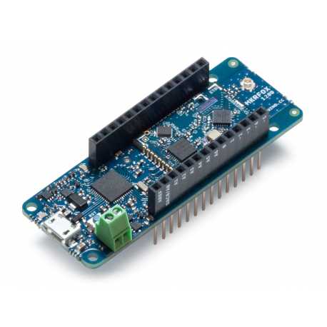
Examples using an Arduino compatible board like MKR FOX 1200
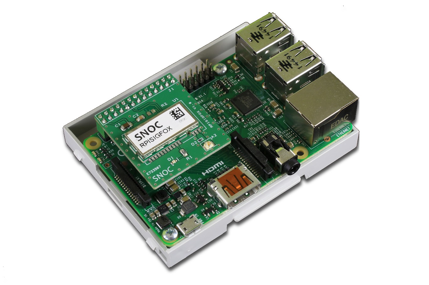
Examples using a Raspberry Pi compatible board like SNOC's expansion board
If you have never worked with these boards before, feel free to choose what suits you best, but know that Arduino and Raspberry Pi are always good starting points for prototyping. They have a large variety of compatible sensors and a lot of available documentation.
Once you get going, try connecting your prototypes to Sigfox's backend and check out the output. To do so here is what you need to know. These links can be very useful:
A Sigfox-ready device incorporates a Sigfox radio module. The module allows it to send and receive messages from the Sigfox antennas. But, in order for that to work, the device has to be activated.
If you buy a ready-to-use device, it will most certainly already be activated.
If you're using a devkit (as the ones here) then you will need to activate it. Follow the very simple steps listed here: https://support.sigfox.com/docs/sigfox-activate:-when-and-how-to-use-it
Your device will have an ID that it uses to identify itself on the network (check for a label on the back of your device with a mention of an ID).
It also uses a second number called Porting Authorization Code (PAC) that you can probably find following these instructions.
These identifiers will come in handy if you want to register your device on Sigfox's backend.
This document explains what Sigfox's backend is and how to use it.
TLDR: It basically allows you to manage all your connected devices, connect new ones and manage how messages received from/sent to your devices should be handled.
Most of your Sigfox-ready devices will come with an app or website that allows you to visualize the data sent by the device. In that case, you don't need Sigfox's backend, since the manufacturer will have taken care of that.

The devices send messages received by antennas > The antennas send the data to Sigfox's cloud (Sigfox's backend allows you to manage what happens from there on) > The data is usually then sent to data visualization apps or trigger an action or a response (downlink)
If your device doesn't come with an app and you need to build one yourself, this is how you do it.
You will have to setup callbacks or use Sigfox's REST API. Learn more on that here.
Once that is set up you will be able to see your messages being sent and decide what Sigfox should do with them (like a manufacturer would do to build their own app).
One of the things you could do with the data sent by your devices is building a dashboard to visualize them.
Two platforms can be very useful for that: Losant and Ubidots. There are many other platforms that can do this, feel free to use the one that you prefer.
By setting up a callback on your Sigfox's backend, these platforms will allow you to process the data sent by your device. For that you will need to know how to parse and decode the data contained in the payload sent by your device (received by the platform).
Use one of these plarforms to build your first complete application with decoding, workflows and data visualization.
How to build a dashboard on Losant to visualize data received through Sigfox callbacks
How to do that with Ubidots
These platforms also allow you to send a downlink message as a response to a callback. To setup that kind of downlink messages follow these steps.
In Losant you can describe what the downlink message should be in the "Webhook reply" block.
For Ubidots, everything is explained here.
In this doc you can see the mention of a "Direct" Downlink mode. If you use that, the data you insert in the "Downlink data in hexa" field will be sent to any device of that Device type that asks for a Downlink message at any time (remember you can only send 6 downlink messages a day per device - and they can't exceed 8 bytes in size).
Remember that a Downlink message will only be sent to your device if your device sent a message with a request for such a response first?
So, you probably what to know how to make your device request a Downlink message now. It might seem a bit technical but it is actually very simple.
For this, you need to know that Sigfox modules usually work with a language that understands what we call AT Commands. This means that if you want to communicate with the module directly you will have to send instructions under the AT command format. For example:
AT$RCwill allow you to reset the module's channelAT$SF=...will order the module to send whatever comes after the equal sign through Sigfox's network
You can usually check what commands are available in your module's documentation (like this one for the Wisol module AX-Sigfox). Some, like the Wisol module, will give you there ID and PAC with the commandsAT$I=10andAT$I=11for example.
In any case, if you want to receive a downlink response to a message sent by your device, you just have to add ",1" to the 12-bytes-max payload you send with the command AT$SF=... (e.g. AT$SF=496F54456173746572456767,1 will send the payload 496F54456173746572456767 to Sigfox's network and request a downlink response).
If you set up the downlink parameter in your backend correctly (as explained above), the device will receive the downlink you wanted it to.
In this repo we will see how to build a simple fingerprint scanner that shows a welcome message on a LCD display after a fingerprint is scanned.
Once the fingerprint is scanned and identified, the device sends the fingerprint ID to Losant through Sigfox. On Losant, a query is done to get the name associated to the said fingerprint ID in a data table. The name is then sent back to the device through Sigfox as a downlink message. Finally, the name is displayed in a welcome message on the LCD display.
To do so, we use an Agile methodology:
%2018.27.26.png)
The first step requires you to think about your idea and structure your thinking before starting developping anything. There are 3 principal questions that you want to get answered:
- What data do you want?
- What do you need your hardware to be?
- How should you store and process the data?
Start with the first question: the best way to answer this question is to ask "What data do I need? What will the data tell me?". Then ask yourself questions like "How frequently do I need data points?" and "What size are the data points I need?". And, finally one of the most important questions: "How should/will my data be used?". Ultimately, question your project and decide if Sigfox is the most appropriate choice or not.
Once you've thought about this, start thinking about how to get the data that you need. This will bring you to thinking about what your hardware needs to be and do: "What sensors do I need? How resistant must my hardware be?"... Search for existing solutions and answer the question "Should I build it?".
And, at the same time, consider the many ways your data could be stored, visualized and analyzed and chose the best one. Ask yourself if the end-user should be able to access the raw data or not; if they should be able to access the data from a phone; if the platform and the hardware need a bidirectional communication, etc.. This will help you understand how your data will be used, what you want to extract from it and therefore what platform you should use to process it.
%2018.28.40.png)
Once you have a very good idea of what you need and what you want to build, start by assembling your hardware. Indeed, this will tell you what the limits of your project are and help you design your firmware and the data workflow.
At the end of the first iteration of this process, you will have built a prototype and will start getting the first results. Visualize and use them. And iterate. After a couple of iterations, you will have conceived a MVP (minimum valuable product). Don't be shy, never hesitate, and deliver too soon! You will get constructive feedback from "Early adopters": use it to iterate and build the product they really need.
In this example, the data needed is the identity of the people getting into a building. It will only be used a few times a day and the data is not heavy, so Sigfox seems like the correct choice. Plus, we will be able to use Sigfox's cloud to send the data to other platforms (to fact check fingerprints for instance). To do so, the hardware will need a fingerprint scanner and doesn't need to be too resistant. So, we can build it easily by using cheap and ready-to-use components that we can buy online. Finally, we will use a LCD display to visualize the data and a platform called Losant to store and process the data, because we don't need heavy data processing but need a platform that is able to send a response back to the device through a Sigfox downlink message.
To build this prototype you will only need a few things:
- A devkit. We will be using NXTIoT's Devkit 2.0, which you can buy here
- A fingerprint scanner. The one used here is Adafruit's fingerprint sensor 751
- A LCD display. Here we use Sunfounder's LCD display (2x16) that you can buy here

- Additionally, we decided to use a photoresistor and a resistor to build a finger presence detector
Connecting everything is pretty simple:
- The fingerprint sensor comes with a 6-cable-cord. You will only need to use 4 of those cables:
%2018.33.05.png)
and connect them in the following manner:
%2010.00.39.png)
- In order to create a finger presence detector with a photoresistor and a resistor, build the following circuit:
%2010.03.26.png)
This will give you an analog reading of the photoresistor's voltage, on the devkit's pin A0. By placing the photoresistor right under the fingerprint scanner's little window, the device will be able to detect a finger being pressed against the scanner, as the photoresistor's value will increase. We use this to activate the scanner only when a finger is detected and, therefore, save some energy.
- The LCD display comes with an I2C Interface Adapter that you will need to solder to the display itself, if it is not already in place. It is pretty straight forward: there are 16 pinholes in the LCD display and 16 pins on the adapter. Holding the LCD display upside down and the adapter facing up, just insert one in the other and solder the 16 pins. You should get something like this:

Then connect the adapter to the devkit like this:
%2010.05.19.png)
Your device should look like this:
%2010.09.32.png)
WARNING!
This firmware has been optimized, but is still very heavy. It is possible that you encounter some stability problems with your devkit once you upload this firmware to it. Indeed, the program uses up a considerable part of the flash memory, and Arduinos don't like that...
You will find the complete and commented firmware here (Spanish version also available here).
You might need to download some of the libraries used if you haven't used them before (click here to see the libraries you need). After that you will just need to upload it to your devkit.
The devkit will wait for a finger to be placed on the finger detector. It will then activate the scanner. Once a fingerprint is scanned and identified, it will add the fingerprint's ID to the payload (buffer) that will be sent through Sigfox.
If the fingerprint's ID is 1 (administrator's fingerprint), the device will give the option to register a new fingerprint or to erase one. According to what the administrator choses to do, a new fingerprint can be added to the device's memory with the ID of their choice; or, a fingerprint can be erased from the device's memory. The administrator's choice and the modified ID (added or deleted) are then added to the buffer. The buffer is then sent as a 3-byte long message through Sigfox.
If the fingerprint's ID is not 1, two bytes representing 0 will be added to the buffer, so the message received by Losant is always the same size, no matter what (this will make the decoding easier on Losant). The buffer is then sent as a 3-byte long message through Sigfox.
The device will then wait for a downlink message containing the person-whose-fingerprint-was-identified's name. The name will arrive as an 8-byte message in HEX format. It is translated into ASCII format so it can be read by a human as normal text.
The name is then showed on the LCD display.
By now you should know how to set a Bidirectional Callback between Sigfox's backend and Losant. You should also know how to set the Downlinks to "Callback" and use Losant to send a Downlink response to your device. If not, read about this here and here.
Once you have set up the bidirectional communication between Sigfox's backend and Losant, you are ready to start using Losant to process the data sent by your device and deciding on what should be sent back as a Downlink response.
The first thing you want to do is create a device on Losant called "Fingerprint scanner", for example. Add the following attributes to it:
%2010.11.18.png)
This will allow you to easily create a dashboard, should you need to visualize these attributes' values, on Losant.
Then, create a "Data table" on Losant that contains the Fingerprint IDs and the names associated to each one of them:
%2010.12.11.png)
Finally, build the following workflow:
%2010.13.35.png)
The webhook will trigger the workflow. The first "Function" block parses the 3-byte long message sent by the device and translates it into the following variables:
- scanned fingerprint ID
- administrator's choice (if the scanned fingerprint ID is 1, the administrator has scanned their fingerprint and decided to add or erase a fingerprint from the device. If not, this will be equal to 0)
- the ID modified by the administrator (the fingerprint ID the administrator has chosen to add or erase. 0 if the fingerprint scanned is not the administrator's)
A query will give us the name associated to the scanned fingerprint in the "Data Table" we created on Losant.
| Getting row (specify query) | Getting row (define result path) |
|---|---|
%2010.15.01.png) |
%2010.15.24.png) |
A "Conditional" block checks if the scanned fingerprint is the administrator's.
%2010.16.40.png)
If so, the workflow continues with a second "Conditional" block that checks if the administrator decided to add or erase a fingerprint from the records.
%2010.17.40.png)
The corresponding action is taken on the Losant's data table (inserted or deleted row)
| Deleting row | Inserting row |
|---|---|
%2010.18.56.png) |
%2011.35.30.png) |
A webhook reply block sends a simple "01" response as a symbol of a successful process.
| Webhook reply block | Reply Body |
|---|---|
%2010.25.28.png) |
{"{{data.body.device}}":{"downlinkData": "0000000000000001"}} |
If the scanned fingerprint is not the administrator's, the device's attributes on Losant are updated.
%2010.22.34.png)
Then, a "Function" block translates the name (that we got from the query) from ASCII format to HEX format (on Sigfox the data has to be transfered in HEX format) and checks that the payload will be exactly 8-bytes long (avoids getting an error from Sigfox).
Finally, a webhook reply block sends the name in HEX format back to Sigfox:
| Webhook reply block | Reply Body |
|---|---|
%2010.23.27.png) |
{"{{data.body.device}}":{"downlinkData": "{{data.body.nombre}}"}} |
Your data workflow is ready!
.gif)
This solution could be enhanced with Losant's numerous possibilities: you could build a dashboard to visualize your data in a completely different and original way, you could add a "Slack" block to your workflow so that an alert is sent to you or someone else on Slack when someone scans their finger, you could set off an alarm on the device if an unauthorized fingerprint was scanned...
Always consider the data you get from you IoT device as the real goal of IoT! Never disregard how the data should be visualized, processed and used after analysis. This data could enhance your security, optimize processes and save you energy, money and time.
Finally, remember to always adopt deliver too soon and use the feedback to iterate.