This is a fully functional prototype of a strobe light for stage lighting that can be controlled by the DMX512 protocol. It is based on the ESP32 microcontroller. The plan is to make it into a full product.
Current prototype in action:

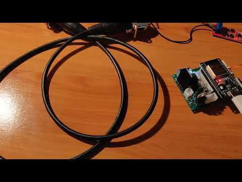
Here is a video of the ESP32 on the mainboard (without the power electronics attached) recieving DMX signal from an Arduino UNO:
In the field of lighting technology, a strobe light or a stroboscope is a device whose task is to create the impression that the movements of objects are jerky or slowed down. It achieves this with rapid flashes of intense light.
DMX512, or DMX (Digital Multiplex), is a standard for digital communication networks commonly used to control stage lighting and effects. It works by transmitting up to 512 control channels (hence the name) over a single data link, allowing centralized control of various lighting fixtures, dimmers, and special effects devices.
The DMX512 protocol is based on the RS485 standard which uses differential signaling with voltage levels typically ranging from -5 V to +5 V. This allows for better immunity to interference and is thus suitable for longer distance communication. Communication is multipoint, enabling multiple devices to be connected to the same bus.
Each channel carries an 8-bit value (0-255), which corresponds to different parameters of the lighting fixture (e.g., intensity, color, position).
A single DMX network, or "universe," consists of 512 channels. Multiple universes can be used for larger setups.
Devices are connected in a daisy-chain configuration using 5-pin XLR cables (although 3-pin cables are also common).
DMX512 has become the standard for stage lighting, but it is also used in architectural lighting or special effects.
This is how the LED reacts to different channel values.
| Channel | Value | Function |
|---|---|---|
| 1 | 000 - 255 | Intensity 0 - 100% |
| 2 | 000 - 255 | Strobe effect speed 1 - 25 Hz |
| 000 - 004 | Blackout | |
| 3 | 005 - 250 | Strobe duty cycle 0 - 100% |
| 251 - 255 | Blinder (Light on) |

The brain of the whole project is a dual-core ESP32 development board, which is seated into a custom made mainboard.


The microcontroller itself cannot receive the DMX signal, which is based on the RS485. The conversion of the RS485 signal to serial, which the ESP can process on one of its UARTs, is provided by a module built with the MAX485 chip.

The ESP has a TC4420 MOSFET driver connected to pin 25. It can very quickly switch the MOSFET IRFZ44N, through which three COB LEDs are connected, with a combined power of 150W.

An iteresting obstacle in this project is the number of voltage levels present in it. The LEDs run at 32V, the fan at 24V, the MOSFET driver should have a voltage greater than 5V, RS485 needs 5V and its logic is five volts, and the ESP32 can be powered with a higher voltage than 3.3V, but its logic will remain at 3.3V. I solved this with different converters and voltage regulators. It is a bit messy, but it's what I already had.
For the power LEDs I use a boost converter module that can handle up to 10A. The module increases the voltage from 24V to 32V.

To get the 9V for the MOSFET and ESP. For this I used a buck converter.

To obtain 5V for the RS485 module, I used a linear voltage regulator called L7805 with two capacitors for voltage stability.
In order to be able to read data from this five-volt module using ESP, I had to add a voltage divider to the data pin, which turned the 5V signal into a 3.3V signal.
I was unable to find a suitable 24V voltage source from which to power the entire device. I had access to a good 28v supply so I used that. But it means that an additional voltage regulator is needed, because the fan for cooling the LED runs on 24V. I didn't have an L7824, so I used an LM317, along with two resistors for voltage adjustment and two capacitors for stabilization. However, I didn't want to complicate the schematic even more, because 24V sources are standard and the fact that I have a 28V source is rather an exception, so I didn't include that there.

This project is made in Visual Studio Code with the Platformio extension which allows easy embedded platform development.
I used the ESP-Prog debugger for hardware JTAG debugging. I also connected the ESP32s RX0, TX0 and EN with it so that I could use the serial monitor. The Platformio debug configuration is reflected in the platformio.ini file.

This project's code relies on the well known Arduino framework and on the Espressif's port of FreeRTOS for the ESP32. FreeRTOS providies multitasking capabilities by running a scheduler that switches between created tasks. It is useful because it allows to efficiently do multiple different things concurrently on the ESP32's dual-core processor.
Learn how the FreeRTOS scheduler switches between tasks here
The FreeRTOS port is compiled in Espressif's ESP-IDF framework, which focuses on the C language. However, I wanted to use an object oriented approach for easier future additions to the project, so I tried to write as much as I could in C++ (this is also one of the reasons for choosing the Arduino framework). Because the FreeRTOS functions are made for C programming, I am using a C++ wrapper library called WrapperFreeRTOS. It made it a little easier to work with, but some workarounds were still needed.
In this case, the program is split into 3 tasks:
LogTask - Handles logging to the microcontrollers UART, which can be recieved in the serial monitor of a connected computer. If other tasks want to log something, they send an entry to this task via a queue.
DmxTask - Uses the esp_dmx library to recieve DMX512 packets from the RS485 to serial module and sends them to the LedControlTask via a queue.
LedControlTask - Reads recieved DMX data from a queue and controls the LED accordingly. It utilizes software timers to create a strobe effect and uses the ledCxxx functions to dim the LED via PWM (pulse width modulation).
main.cpp - The core of the program.
deviceConfig.hpp - Configuration file for things like pin numbers or LED parameters.
logTask.hpp - Header file for the logging task.
logTask.cpp - Implementation of the logging task.
dmxTask.hpp - Header file for the DMX512 recieve task.
dmxTask.cpp - Implementation of the DMX512 recieve task.
ledControlTask.hpp - Header file for the task for led control.
ledControlTask.cpp - Implementation of the task for led control.