
This project is intended to provide an graphically customizeable and functional firmware to drive PX LED Matrix panels and other common displays using ESP8266 based microcontrollers. It's powered by the PxMatrix and Adafruit display drivers. The project gained inspiration from [MorphingClockRemix](https://github.com/lmirel/ MorphingClockRemix) and is intended to greatly expand upon it's functionality, providing an easily end-user customizable system using a JSON based configuration system and a Vue based web interface. This is one of my first substantial C++/HTML projcts, so some aspects are still a bit rough. The name itself is a placeholder until something clever comes along.
- Integrated web dashboard
- Drag and drop widget based display configuration
- Built-in image editor with support for standard images and binary formats
- Several display brightness control modes
- NTP time synchronization and timezone support
- OpenWeatherMap synchronization
- OTA Updating
- Raw configuration editor
- YouTube subscriber counter
- Tetris Animation font

A demo of the web dashboard is available Here. Example data is provided in place of the normal display API calls. Aside from configuration and image saving, the dashboard should be fully functional.
ESP32 and ESP8266 are now fully supported. 4MB of RAM is required to use both the web dashboard and OTA updates.
Any panel configuration supported by PxMatrix should be supported, but pre-built binaries are only availible for a few display sizes such as 32x64. Most of development was on P3 and P4 32x64 panels, so that size is best supported. Wire the display based on this. The PxMatrix alternate SPI mode is used by default for ESP32 to account for displays that don't have the normal SPI pins broken out.
Any SSD1306 displays compatible with the Adafruit SSD1306 driver should be fully compatible, though pre-built binaries are again only availible for certain display resolutions, such as 128x64. For compatibility reasons, images aren't stored in a monochrome format. In SSD1306 display mode, colors are treated as black or not black when rendering, but still use 16bit colors.
A photoresistor/resistor is supported on pin A0 in this configuration to control the display brightness. The sensor value can be viewed in the Dashboard page of the web dashboard.
The full release binaries can be flashed using esptool or a GUI version. For esptool's command line interface:
# Example command for NodeMCU V2
esptool --port /dev/ttyUSB0 write_flash -fm dio 0x00000 nodemcuv2-32x64-v1.bin

# Example command for NodeMCU 32s
esptool --port /dev/ttyUSB0 write_flash -fm dio 0x10000 nodemcu-32s-32x64-v1.bin
Alternatively, you can use Platformio or Arduino
IDE after downloading the latest release
source code.
The flash memory split for the program and filesystem is 1 to 1 to 2 for a 4MB board, where 1MB is for the program, 1MB is
for firmware OTA updates, and 2MB is for the LittleFS filesystem. For ESP8266 with platformio, this means the
eagle.flash.4m2m.ld ld
script. For Arduino IDE, use the 4MB (FS: 2MB) flashing option. For ESP32, a custom partition file is needed if the
default flash layout doesn't suit your needs.
Manually compiling the firmware and building the dashboard is only required if not flashing one of the pre-built full binaries that contains both the firmware and dashboard. The dashboard is built and moved to the data directory by running the following scripts in the project directory. This must be done before uploading the filesystem image to the ESP8266.
# Install NPM dependencies
./install-dependencies.sh

# Build the web dashboard
./build-dashboard.shTo use Arduino IDE, the following libraries must be installed through the library manager:
- PxMatrix (If using a PX panel)
- Adafruit SSD1306 (If using an SSD1306 OLED display)
- Adafruit GFX Library
- ESP_DoubleResetDetector
- ESPAsyncWiFiManager (Manually install)
- ESPAsyncTCP (If using ESP8266, manually install)
- AsyncTCP (If using ESP32, manually install)
- ESPAsyncTCP (If using ESP8266, manually install)
- ESPAsyncWebServer (Manually install)
- ArduinoJson
- ezTime
- RunningAverage (If using brightness sensor "rolling" average)
- TetrisAnimation (If using Tetris font)
Due to Platformio compilation issues when using .INO files directly, the main.cpp must be renamed to display.ino before opening the project in Arduino IDE. All board specific definitions in platformio.ini must be changed in the new .INO file if your board isn't a 4MB ESP8266 board.
The ESP8266 board support must be installed from here. The ESP8266 FS plugin is also needed to upload the web interface. Select the correct board and flash split for your board. First upload the code to the board, then select FS Data Upload under Tools. The 4MB (1MB FS) flash option must be selected.
If using ESP32, add boards using this and use the FS plugin from here. A custom partition layout is used for the project, so the included partitions.csv file needs to be copied to ~/.arduino15/packages/esp32/hardware/esp32/1.0.4/tools/partitions/ for Linux, for example. The boards.txt file at ~/.arduino15/packages/esp32/hardware/esp32/1.0.4/boards.txt needs to have the following added:
esp32.menu.PartitionScheme.display=Display Layout
esp32.menu.PartitionScheme.display.build.partitions=partitions
The ESP32 Dev Module board must be used to select the Display Layout partition scheme. Then, run ESP32 Sketch Data Upload under Tools.
To use Platformio, install it and configure platformio.ini to suit the display size and ESP flash layout. If you are using one of the boards with a pre-configured environment, just use that one, especially since that will enable easy OTA updates using release binaries rather than manually compiling and flashing new ones. Build and upload to the board. Then run the Upload Filesystem Image task.
This project uses ESPAsyncWiFiManager to handle WiFi configuration. After successfully connecting to a network using the created access point, the display's IP will be shown. The configuration server is hosted on port 80, so enter the address in any browser. After saving any configuration from the Display page, the display will update and show the new content. ESP_DoubleResetDetector is used to detect two restarts within ten seconds of each other, at which point the WiFi configuration AP will start again. The configuration screen is always displayed after setting up the WiFi connection, if you want to determine the display's IP. Static IP configuration is not available yet. If the display isn't displaying correctly after flashing the firmware, the default PxMatrix parameters may be incorrect for your display. In this case, either determine the IP of the display using a serial monitor with baud rate 115200 or your router. Once connected to the display dashboard, try changing the mux and scan patterns under Settings. If this doesn't fix it, the wiring may be incorrect, or the firmware wasn't correct for your board, causing incorrect pin assignments.
Vue is used to create a SPA webpage that is hosted on the display. All files are compressed and it takes up about 500KB of the filesystem. The first time loading the interface takes a while, but after that the files should be cached until the dashboard is updated. All of the resource intensive processes like image conversion take place in the browser to leave only rendering to the display. The dashboard should be fully functional on either mobile or desktop environments, but the mobile part is not seamless yet. The interface is broken up into several pages based on their functions. The sidebar handles navigation between pages, and the page names should be pretty self-explanatory.

OTA Updates are as simple as downloading the newest release binary that matches your board configuration and selecting it from the OTA Update page of the dashboard. Alternatively if you have a non-stock configuration, pull the repo changes and build and deploy the dashboard and firmware again. The dashboard can also automatically download and flash the latest binaries if you are using a stock configuration.

Ensure that you download a backup of the configuration before updating, otherwise all configuration settings and custom images will be lost. This can be done in the Backup page. After updating, simply upload your backup and everything should be restored.
If the dashboard website finishes loading but has a blank screen or the display unexpectedly needs configuration, the flash filesystem could have been corrupted. To re-install the dashboard, visit http://{display-address}/recovery to upload a filesystem binary from the Releases Page. Flashing the display in this manner will erase all custom images and configuration settings, just like a normal OTA update. The display will not turn off when flashing from the recovery page, so you may want to cover the display to prevent strobing. Custom images can manually be recovered if only the dashboard was corrupted. Visit http://{display-address}/images to get a JSON file containing all stored images. Visit http://{display-address}/image?image=blm to download a binary file for image blm, for instance. This can be re-imported using the images page after the dashboard is re-installed.
The display configuration is entirely based on a JSON configuration file stored in the display filesystem. This is
primarily intended to be configured using the graphical interface, but the Raw Configuration Editor page can be used
to directly edit the JSON file. If the dashboard isn't required, the configuration files could manually be uploaded
using the data directory. configuration.json is used to store the display configuration, and images.json stores
the properties of custom images.
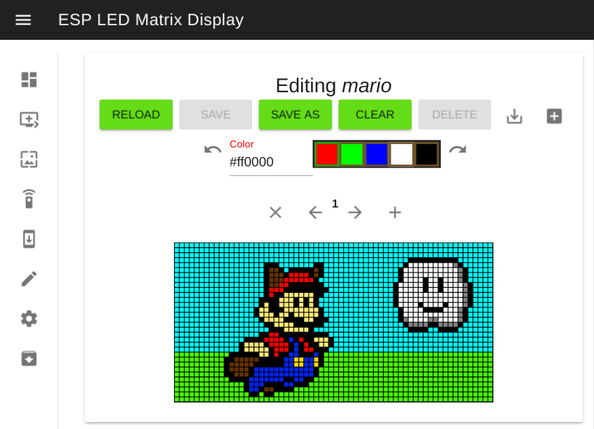
The Image Editor page houses a basic image editor that can be used to import and pixelate custom images, or copy and edit built-in images. More features are to come like copying and pasting image frames, a bucket tool, and an eye dropper tool, but it is perfectly adequate for importing and editing pixel art type content. The image editor is also where you can download images to a variety of useful formats, including raw 565 binary, Gimp header, PNG, and JPG, so it also serves as an image converter.
All text based widgets have three font types. The tiny font uses the TinyFont library from MorphingClockRemix. The TetrisAnimation font looks cool and creates the text using Tetris blocks. The rest of the font sizes use the default Adafruit GFX printing font scaled different amounts. They can be freely resized and the text content will be centered. Supports word and character wrapping for non-tetris fonts.
- Text: This is a basic Text widget that shows a static string.
- Digital Clock: This widget shows the current time in 24 hour, 12 hour, or 12 hour with period formats.
- JSON GET Text: This sends a GET request and parses a JSON response to display. Supports HTTP and HTTPS.
- GET PLAIN TEXT: Sends GET requests and shows the body of the response. Supports HTTP and HTTPS.
There are two types of images to display: custom images provided by the user and build-in images. The built-in images are read-only at runtime, but more can be easily added by customizing the source code. The dimensions of image widgets are fixed to the size of the image content. A few animations are availible that scroll the image across the screen in each direction.
These components show a simple animation based on the current weather state from OpenWeatherMaps. The API key and location need to be configured on the Settings page.
This is a scalable widget that draws a clock based on the current time. All time based widgets update ten times per second, so the maximum re-draw latency is 100ms.
These are static shape widgets that can be outlines or filled in.
Availible shapes:
- Rectangle
- Rounded Rectangle
- Circle
- Pixel
This project is intended to handle everything in a more asynchronous way to ensure consistent rendering. Previously, I attempted to branch MorphingClockRemix with a few more features, but it was fundamentally designed differently, where animations would steal the main thread until they were done, which isn't really compatible with my idea for a widget based rendering system. Thus, I started from scratch.
Depending on your configuration, up to three display buffers could be used. One or two buffers will be used by PxMatrix to handle basic rendering, but another buffer will be allocated if any enabled widgets are using transparency. This works by rendering all background layer widgets to this buffer and then drawing a portion of this buffer underneath any dirty widgets. If a widget isn't using transparency, then the specified background color will be filled underneath the widget according to its size. There is a tradeoff here: a lot more memory is required, but the need to re-draw the entire screen is greatly reduced, only occuring when a background layer widget changes. Widgets are rendered from lowest layer to highest layer, but background layers should not be above any non-background layers or things will render incorrectly.
Widgets are marked as dirty whenever their content changes. This can happen if they are a time based widget and the time changes or if they are a dynamic widget and the specified update interval elapses.
There is a basic, unsecured API that the dashboard uses to configure the display. This is defined in the setupWebserver function, and functions for each route can easily be read to determine any necessary parameters. Token based or basic auth could be a future feature.
It's recommended to use Platformio if you are planning on customizing the firmware.
The definitions are all documented in the source code. The following definitions are configured in the platformio.ini file if using Platformio. Just change the source definitions if using Arduino IDE.
- VERSION_CODE: This is used to update dashboard browser caches and ensure that the dashboard version always matches the firmware version so that hopefully no broken configurations occur.
- DISPLAY_WIDTH: The width of the display. Used for buffer sizes and configuration thresholds.
- DISPLAY_HEIGHT: The height of the display.
- DISPLAY_PANELS: The total number of chained horizontal panels.
- DEBUGGING: Enables more verbose logging of display events to the serial port.
- Brightness Sensor: If the brightness sensor is enabled, the Vcc measurement is disabled. If the brightness rolling average is disabled, a bit of memory will be saved and the display will immediately respond to brightness changes. This is enabled by default.
- Arduino OTA: This is really only useful for LAN based development, since it doesn't want to flash the FS binary directly over the existing filesystem, presumably, since it complains of not having enough space.
- Web Server Caching: Files are cached based on dashboard version, so if you are modifying and testing the dashboard, you may want to disable this.
- Double Buffering: The PxMatrix library supports using two buffers, with one being the actively rendered buffer and the other being the one being drawn to. This prevents partial renderings of content until the entire screen is done drawing. The downside is that twice as much memory is used for display buffers. This is enabled by default.
- TetrisAnimation Font: There are a few significant reasons to disable this. The library was not written in a way that supports double buffering, causing a shadow effect if using double buffering. In addition, just having the library enabled uses a ton of memory for an ESP8266: around 10KB, which ideally would have been stored partially in PROGMEM, but re-writing the entire library isn't really an option. The library also leaks the drawn characters into the Serial stream, which isn't ideal, either. It's a very cool looking animation, though.
Additional images can easily be added to the firmware by including the source header for either images stored as a uint8_t, uint16_t, or char(Gimp) array. To make the display aware of the images, simply add a new entry to the progmemImages map with the correct type, dimensions, and a name. 565 color and Gimp header files are supported. Both of which can be exported from the dashboard. The 565 format uses half the space that the Gimp format uses, so it is preferable. Unwanted included images can also be removed in this way.
- Tiny font and weather animations are repurposed from MorphingClockRemix
- BLM and Mario images are from PxMatrix
- Gimp header format information is from Disk91
- 565 Image format based on this converter