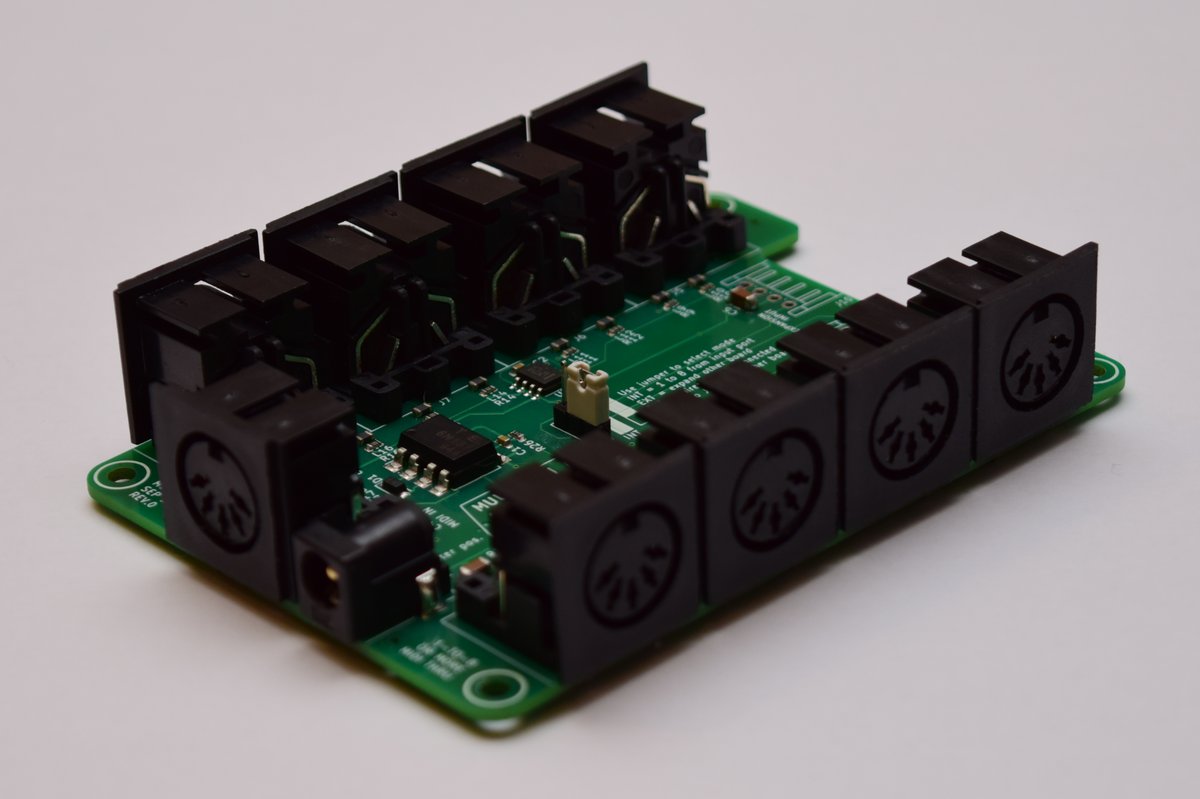
Multi-MIDI is a 1-to-8 or more MIDI thru box. This is definitely not a novel idea, but it's mainly for fun and to keep it cheap. Everything here was made with open source software and with the publicly available MIDI specifications.
All the files are available, so you can make your own. In brief, what you'll need to get the full thing:
- Have the circuit board manufactured; we usually used JLCPCB for this, who also can do assembly of the surface-mount components
- Get all the components; if you went with assembly by JLCPCB, you only need to get the DIN-5 connectors, barrel jack, and 3-pin header. A full bill of materials is below.
- Get the 3D printed case; either if you have access to a 3D printer, or get some online service to make it for you
- 4 heat-sinkable threaded inserts
- 4 10mm long M3 screws
- Soldering iron
- Screwdriver
- 5V power supply with centre positive barrel connector (2.1mm pin, 5.5mm diameter)
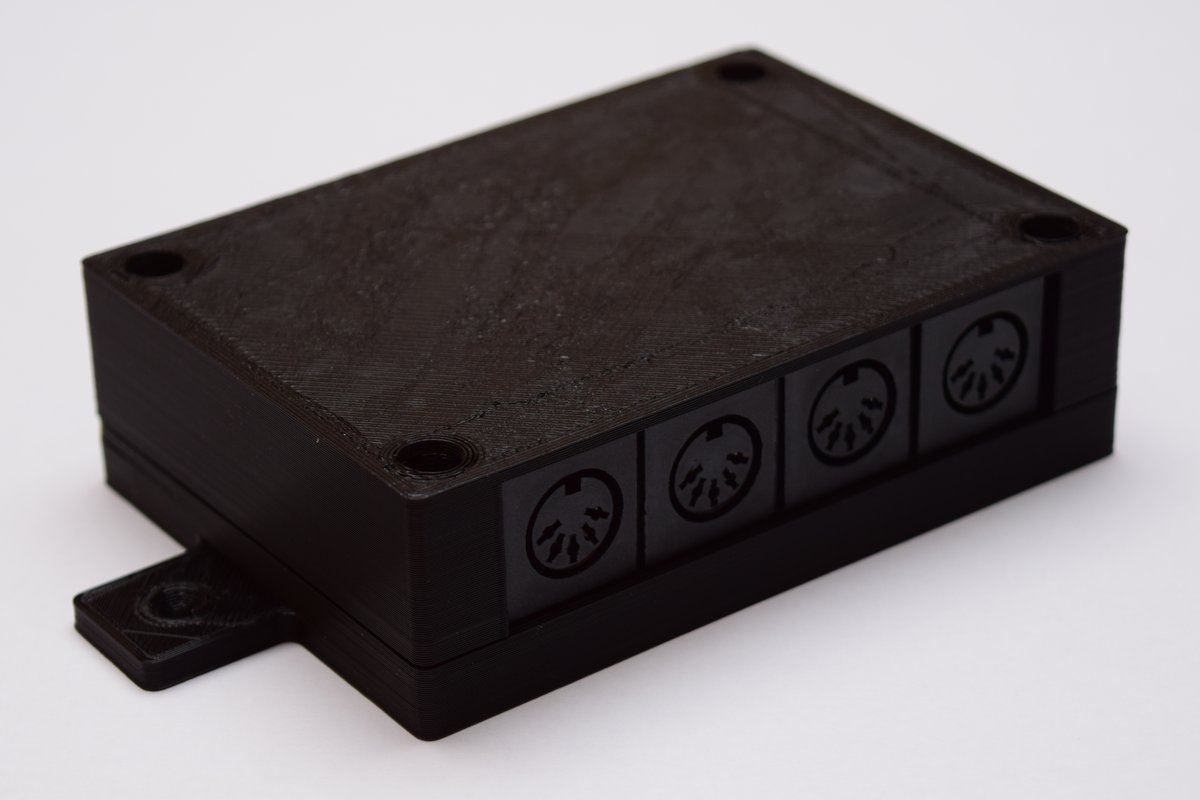
The tab shown above is for mounting, for example, to the back of a cabinet.
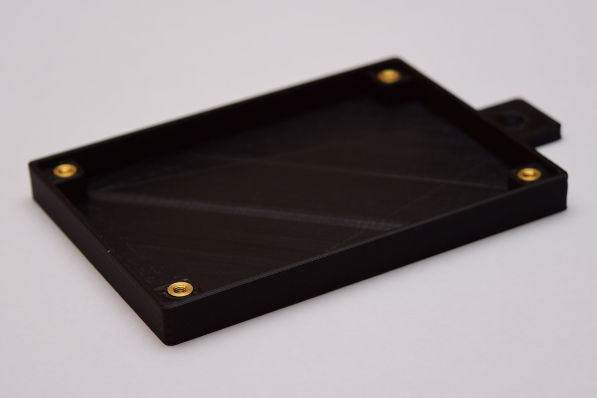
Heat-set threaded inserts go into the bottom part of the case's screwholes, allowing the use of M3 machine screws to assemble the box.

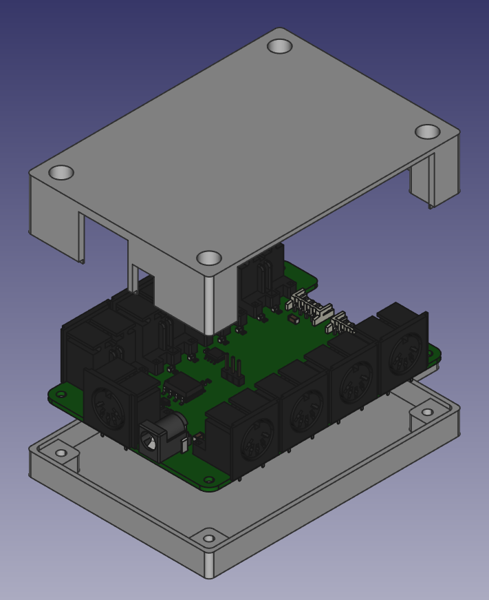
Exploded view of the case and circuit board, in FreeCAD
The least-work way is to order the Printed Circuit board (PCB) assembled from JLCPCB. You can also order a bare board from any PCB prototyping place, and then source and solder all the components yourself.
-
Go to the Latest release and download the .zip file ending in
.gerber.zip. This contains all the PCB fabrication outputs from KiCAD. Alternatively, clone or download this repository, open the project from the pcb/multi-midi folder in KiCad and export the gerber files yourself. -
Download the BOM file, ending in
.jlc.bom.csv. This contains a list of all the parts that JLCPCB will supply and install themselves. -
Download the "centroid" position file, ending in
.jlc.top-pos.csv. This contains the positions and orientations for the parts JLCPCB will assemble.
If you want, you can generate the latter two files yourself, but this is trickier than generating the gerber files since a 3rd party script needs to be installed, and output files manually edited to work with JLCPCB. Documentation: How to generate the BOM and Centroid file from KiCAD
- Go to JLC's ordering page
- Click "Add your gerber file", select the
.gerber.zipfile from above - Pick a board color or leave it at the default green. Last time I checked different colors only affect build time, not price.
- Pick a surface finish or leave it on the default. The default is cheapest, but contains lead. ENIG gives the pads a nice golden finish instead of silver.
- For "Remove Order Number", pick "Specify a location"; this means they'll print the order number where the board design says "JLCJLCJLCJLC" (on the underside of the board) instead of a spot you don't control.
- Leave all the other options as they are.
- Scroll down to "SMT Assembly" and switch it on
- Select "assemble top side"
- Pick a quantity; if you only want one, 2 will be the minimum here
- Click "Confirm".
- On the right side of the page, click "Next"
- Click "Add BOM File"; upload the
.jlc.bom.csvfile - Click "Add CPL File"; upload the the
.jlc.top-pos.csvfile from earlier - Click "Next"
- Review the specified parts; they should all be "confirmed" in the right column, so you can leave everything as it is.
- Click "Next"
- In the preview, some ICs might look like they're oriented wrong. This is a problem with their viewer; the files are correct. If it ends up wrong (not aligning with the pads), they'll either correct it or email you to find a solution.
- Click "Save to cart"
- Click "Check out Securely"
- Add your shipping and billing details
- Select a shipping method. Usually the DHL-based ones are fine. You can gamble on whether or not you want duty and customs paid up front (more expensive), or hope for the best with the cheaper option, in which case you might get a bill from the courier later.
- Click "Continue" when you're happy
- Click "submit order"
- Do what you need to do for payment
- Wait for your boards to get delivered
The remaining parts are as follows:
- 9x DIN-5 connector:
Deltron 671-0501or equivalent. Some possible sources: - 1x Barrel jack:
Wurth Elektronik 694106301002Some possible sources: - Generic 2.54mm pitch single row pin header - you can find this in any electronics store, eBay, or Amazon. You can get any number of them and use pliers to break 3 pins off.
- Generic 2.54mm pitch jumper; a piece that connects two pins together. You can get these from many places too, but here are some sources:
If you plan to connect more than one board together, you'll also want some connectors for the right hand side:
-
2x JST PH 4 way Right angle connector:
JST S4B-PH-K-S(LF)(SN)Possible sources: -
8x JST PH Crimp contact
JST BPH-002T-P0.5SPossible sources: -
Wire (24 AWG thickness), enough for 4 lengths of however long you want the connecting cable to be - can be found on eBay, Amazon, various electric supplies stores
-
A crimping tool like
Fdit SN-28B
Alternatively, find some pre-crimped cables, possibly on aliexpress; then you don't need the crimp contacts, wire, and crimping tool.
Fairly evident where each of them go, though a more detailed guide here could be helpful. Pull requests welcome. :-)
If you're not planning to expand the board with another, you can leave out the JST connectors. In stead of the 3 pin header + jumper, you can use a spare piece of wire or component lead cutoff, and connect the bottom two holes for the pin header connector that way.
On the pin header in the middle of the board, push a jumper down over the bottom two pins, as demonstrated on the board, for "INT" mode.
To power this thing you need a power supply that outputs 5V. The rated current is pretty irrelevant as this circuit will not draw more than 100 milliamps. To be compatible with the barrel jack on the board, it needs a barrel connector with a pin size of 2.1mm (2mm works too) and outer diameter of 5mm. It needs to be center positive. Generally can be found on eBay or Amazon or any number of places. One of those with switchable connectors can also work. A USB charger + a USB->barrel connector cable would also work just fine.
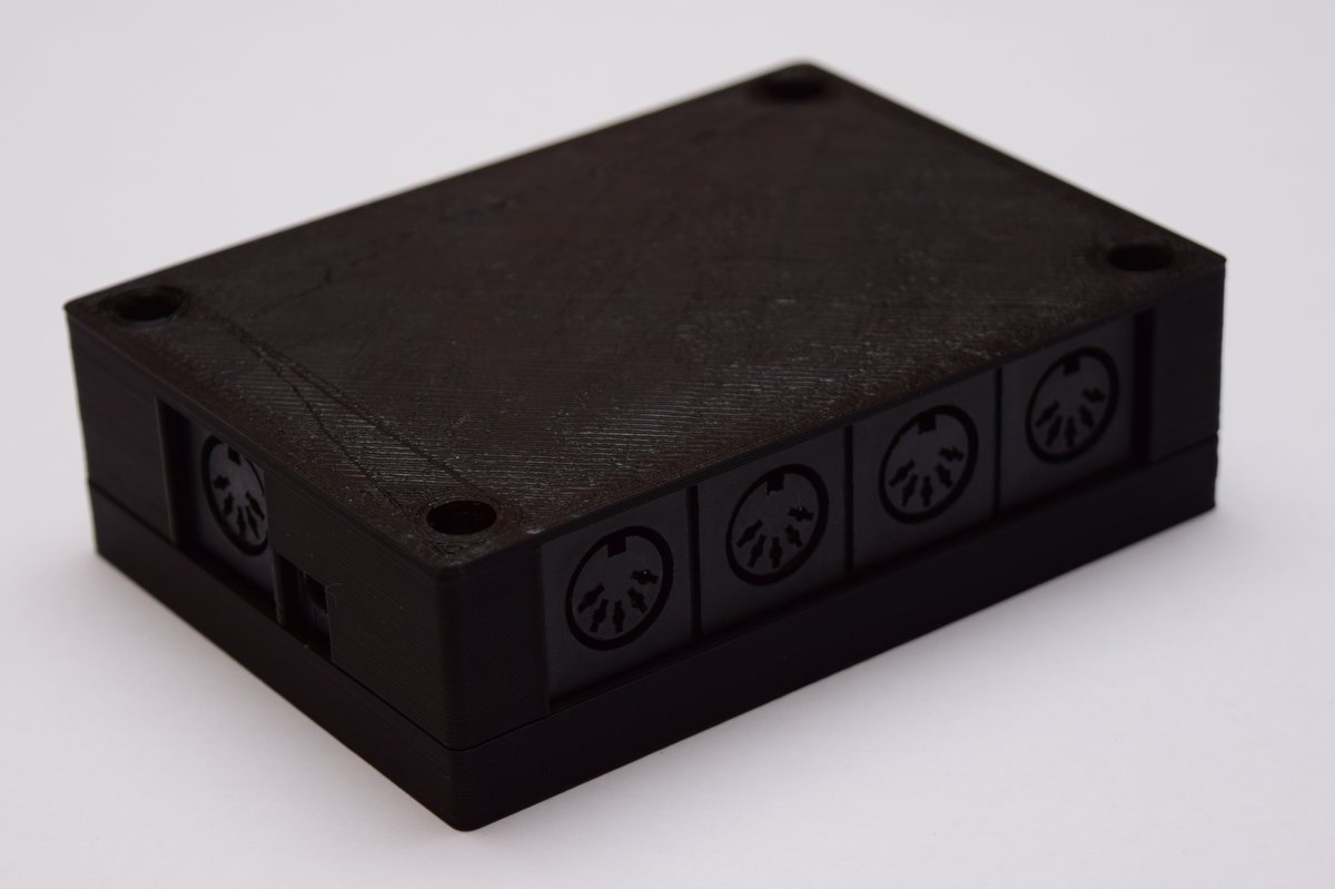
- Download the .stl files from the latest release (where you found the PCB manufacturing file). There are two of them, one for the top portion of the box, and one for the bottom.
- If you have a 3D printer yourself, use your favorite slicing software (like Cura or Slic3r) to generate the .gcode files appropriate for your printer, and start the print job. Note that you may have to turn the top part upside down so the flat side faces the printer surface. If you don't have a 3D printer, either ask a nearby maker/hackerspace or a friend for help, or find an online service that will send you the printed parts. An online search for "3D printing service" should get you what you need.
- Get some M3 heat-set threaded inserts. The ones in the pictures are about 6mm tall. You can find various ones on Amazon and eBay; it mostly matters that they're M3.
- Using small pliers and a soldering iron set to ~200 degrees Celcius, gently insert them into the holes on the bottom part of the case
- Put the finished circuit board on the bottom portion of the case (where you've just installed the inserts)
- Put the top side on, fitting it in the bottom. This may take a little bit of pushing as it's a fairly tight fit.
- Insert 10mm long M3 screws into the screwholes on the top and tighten them
- All done.
Let's first define a few terms:
- MIDI source: The device you are sending MIDI data from. This could be a MIDI keyboard, or a MIDI interface connected to your computer.
- Multi-MIDI: The device this page is all about
- Multi-MIDI input: The MIDI connector on the short side of the Multi-MIDI
- Multi-MIDI output: any one of the 8 other MIDI outputs on either long side of the Multi-MIDI
- Instrument: A device you want to send MIDI data to, such as a synthesizer, digital piano, drum machine... as long as it has a "MIDI in" port.
With that out of the way, here's how you use the Multi-MIDI:
- Connect your MIDI source's "MIDI out" port to the Multi-MIDI input with a DIN-5 MIDI Cable
- For each of your instruments connect its MIDI in port to one of the Multi-MIDI outputs
- Connect the power supply to the Multi-MIDI.
- Consult the manual of each of your instruments to configure which MIDI channel it should listen to. This is a number from 1 to 16.
- On your MIDI source, assign the same channel numbers to the tracks/channels/... so they correspond to the right instrument
- Now you can use all those instruments from one MIDI source.
If you have two of these boards, you can connect them together in 2 possible configurations:
- Expander: This effectively turns the combination into one 1-to-16 MIDI thru box
- Power supply sharing: The devices work independently, so there are 2x 1 to 8 expanders, but only one power supply needs to be connected.
Let's define "board 1" as the first board where you've got MIDI input and the power supply connected.
"Board 2" will be the one we're connecting up to board 1 to expand its functionality.
Note that at this time, there is only a case design for a single board. If you decide to stack more than one board to create an expanded device, you may want to adapt the case design to be larger, to accomodate both. There is a clearing provided in the PCB design to allow connecting cables between the boards internal to a box, for this purpose.
- On board 1, connect the jumper in "INT" mode. This will make it use its own MIDI in port as the source of MIDI data.
- On board 2, connect the jumper in "EXT" mode. This will make it use MIDI input coming through the 4-pin JST connector.
- Connect a cable between board 1's "Expansion output" connector and board 2's "Expansion input" connector
- Connect your MIDI source's "MIDI out" port to board 1's MIDI input
- Connect each of your instruments: connect their MIDI in ports to one of board 1's or board 2's MIDI outputs.
- Connect the power supply to board 1's power input
- On both board 1 and board 2, connect the jumper in "INT" mode. This will make both of them use their respective MIDI input ports
- Connect a cable between board 1's "Expansion output" connector and board 2's "Expansion input" connector
- Connect your first MIDI source's "MIDI out" to board 1's MIDI input
- Connect your second MIDI source's "MIDI out" to board 2's MIDI input
- Connect each of your instruments: connect their MIDI in ports to one of board 1's or board 2's MIDI outputs, choosing between the boards depending on which source you wish to connect to
- Connect the power supply to board 1's power input
At this time, it's unknown what common issues might occur in this process. If you're having any issues, please open an issue on GitHub and we can help resolve it / potentially improve documentation.
A CSV file for this table is also available in the release downloads.
| Quantity | Reference | Value | Footprint | LCSC Component No. | Mfr. Part No. |
|---|---|---|---|---|---|
| 4 | C1 – C4 | 100n | 0603 / 1608Metric | C14663 | |
| 2 | C5 - C6 | 47u | 1206 / 3216 Metric | C96123 | |
| 1 | D1 | 1N4148W | SOD-123 | C81598 | |
| 2 | J10 - J11 | Conn_01x04_Male | JST_EH_S4B-EH_1x04_P2.50mm_Horizontal | JST S4B-PH-K-S(LF)(SN) | |
| 1 | J12 | Barrel_Jack_Switch | BarrelJack_Wuerth_6941xx301002 | Wurth 694106301002 | |
| 1 | J13 | Conn_01x03_Male | PinHeader_1x03_P2.54mm_Vertical | ||
| 9 | J1 – J9 | DIN-5_180degree | Custom: Deltron 671-0501 | Deltron 671-0501 | |
| 18 | L1 - L18 | SDFL2012S100KTF | 0805 / 2012 Metric | C1046 | |
| 17 | R1 – R17 | 220 | 0603 / 1608 Metric | C22962 | |
| 1 | R26 | 10k | 0603 / 1608 Metric | C25804 | |
| 2 | U1 – U2 | LM358 | SOIC-8_3.9x4.9mm_P1.27mm | C7950 | |
| 1 | U3 | 6N137 | SSO-8_6.7x9.8mm_P2.54mm_Clearance8mm | C110020 |
As per the MIDI electrical spec, a MIDI input should be driven through an opto-isolator. In this case that's the 6N137. The MIDI input signal
drives just the LED in the opto-isolator, so it is completely electrically isolated from the rest of the circuit.
D1 is a protection diode, connected the opposite way compared to the opto-isolator's diode. This provides a short-circuit path in case the incoming MIDI is polarised the wrong way,
ensuring the opto-isolator doesn't get reverse-biased, and potentially broken.
The output of the opto-isolator is connected to opamps (LM358) set up in a voltage follower configuration. These act as buffers for the signal, able to drive a bit more current than the opto-isolator can supply. The circuit is set up to supply the signal for 2 outputs per voltage follower; so for all 8, 4 opamps are needed.
Further, there are 220 ohm resistors to limit the current through the opto-isolator diode on the receiving end, as well as small inductors which are meant to filter out high frequency noise, such as from low quality power supplies.
A jumper in the middle of the board selects which source of MIDI should be buffered out to the output ports. Either "INT" (MIDI coming in from the on-board MIDI in port through the opto-isolator, or "EXT", coming in through the "Expansion input" connector. Not connecting a jumper to either will result in no MIDI making it to the output ports.
- The 3D model of the barrel jack used on the PCB design was made by DL2DW - Dirk Wouters and can be found here: Power Barrel Connector Jack on GRABCAD
- The circuitry for single MIDI thru is taken almost directly from the MIDI DIN electrical specification.
- KiCad was used for the electronics design (schematic, circuit board)
- FreeCAD was used to model the case, as well as the 3D representation of the DIN-5 connectors used in the 3D render of the PCB.