Open this page at https://iowadave.github.io/pxt-makerbit-esp12/
This repository can be added as an extension in MakeCode.
- open https://makecode.microbit.org/
- click on New Project
- click on Extensions under the gearwheel menu
- search for https://github.com/iowadave/pxt-makerbit-esp12 and import
My sister's son is an aerospace robotics engineer. His capstone project as an undergraduate was to build an orientation mechanism to keep a satellite aligned with the Sun.
He solved the problem with two Arduinos working cooperatively: one handled all the sensors, the other operated the mechanism.
The two microcontrollers communicated via their serial ports.
Wow! I thought. Very cool. Then a friend, Roger Wagner, asked whether MakeCode could be used to program an 8266 microcontroller. I remembered my nephew's satellite and said, "Why not?"
Strictly speaking the answer is No, because MakeCode does not support the 8266 directly. However, the answer becomes Yes when you connect the 8266 to one of Roger's MakerBits.
All it would need is a firmware on the 8266 that can receive, process, act upon and respond to commands sent by MakeCode running on the MakerBit. And then, how nice to have a set of custom blocks for sending the commands and receiving the responses.
This Extension package provides the custom blocks.
Note: The blocks and functions defined in this code are designed to communicate via serial with custom firmware installed on an Expressif 8266 microcontroller, in particular the models ESP-12E or -12F, mounted on a development module such as a NodeMCU or Wemos (Lolin) design.
You will need to install suitable firmware on the 8266 separately. An example can be found on github at https://github.com/IowaDave/8266-Firmware-for-MakerBit.
A Companion Board for the 8266 can support direct connection of many devices and sensors to the 8266. It gives MakeCode the power to control more sensors and actuators than could connect to the MakerBit alone.
A tutorial for how to make a Companion Board is available on the firmware's web page, https://iowadave/github.io/8266-Firmware-for-MakerBit/.
Also, you will need to connect the MakerBit to the 8266 Companion Board via the devices' serial I/O pins. This article assumes that you will choose the default pins, as described in the tutorial mentioned above.
This is done with a block from the Serial group, found in the Advanced list of standard blocks. Figure 1 shows MakeCode instruction for using pins P0 and P1 for serial communication. Those pins are the default serial pins for the MakerBit.
[Figure 1]
You must import the blocks before you can use them, as explained above in "For Use as a MakeCode Extension".
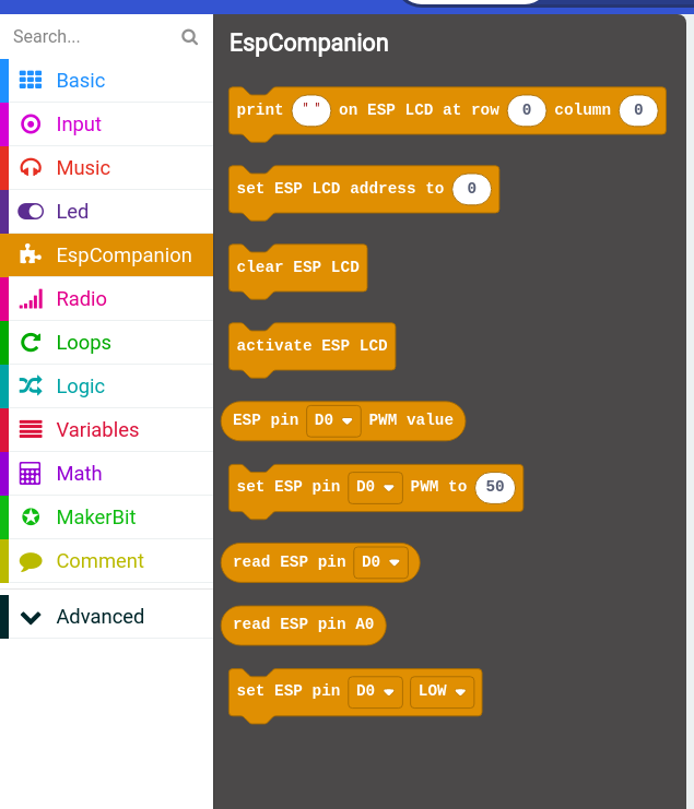
Figure 2 shows the package of blocks as it appears on the List of Blocks after being imported. It is named, "EspCompanion".
Clicking on the name in the list opens a popup menu that lists the blocks available.
[Figure 2]
The blocks group into several categories. The following descriptions and examples will be organized by groups.
These blocks work with the digital pins on the 8266. The blocks allow you to set the value of a digital pin or to obtain the current value of a pin. Figure 3 displays the blocks.
[Figure 3]
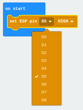
Figure 4 shows an example of using a block to set the value of digital pin D5 to "HIGH". The block includes a dropdown list of the digital pins on an ESP-12E or ESP-12F module. It also has a dropdown (not shown) for choosing between the "HIGH" or "LOW" setting.
[Figure 4]
About Digital Pin Values
In the digital world everything is a number. Words such as "HIGH" and "LOW" have meaning only as names for numers. The blocks in this Extension package translate the word HIGH into the number 1, and the word LOW into the number 0.
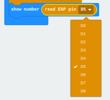
Figure 5 shows an example of using a block to obtain the value of digital pin D5 and then to display it on the micro:bit's LED panel.
This block is an oval-shaped "reporter" block that returns the value as a number. It can be used anywhere that a numeric variable would be expected. In this example, it is used in the basic "show number" block.
The number will be 1 when the pin is set to HIGH. It will be 0 (zero) when the pin is set to LOW. Reading the value of a pin does not change its value.
Again, the block features a drop-down list of the digital pins on the ESP-12E or ESP-12F module.
[Figure 5]
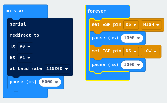
Figure 6 shows a simple "Blinky" sketch that lets MakeCode program an action on the Companion Board. It turns the LED on and off. This algorithm has gained the cult status of the famous "Hello World" program, but for microcontrollers rather than computers.
The "pause" block in the startup block only runs once. It allows time for the CompanionBoard to complete its internal startup procedures. This practice may be advisable when both devices will be started simultaneously.
[Figure 6]
There is just one block related to the analog input pin, A0. It is oval-shaped and returns a number in a range between 0 and 1023, derived from the voltage being sensed on that pin. Figure 7 illustrates the block being used to print the value on the MakerBit's LED display.
[Figure 7]
There is no drop-down list of analog pins for this block, because the 8266 supports only a single analog input, which is A0.
Watch out! Some ESP-12-type modules can tolerate a maximum of only 1 volt on pin A0. Others can tolerate up to 3.2 volts. Your module may vary. Concepts for controlling the voltage of a circuit are outside the scope of this article.
Pulse wave modulation is a digital technique that gives results similar to a dimmer switch or a motor speed control. The 8266 can perform PWM on all of its digital pins. Figure 8 shows the blocks for setting the PWM level of a digital pin.
[Figure 8]
This article does not try to explain how PWM works. The Web crawls with tutorials and articles about PWM. The example that follows might "illuminate" the topic.
The firmware we wrote to work with these blocks adjusts the 8266 so that its PWM levels range between 0 = "off" and 100 = "fully on". That is why the block to set a PWM value accepts a number in the range of 0 to 100.
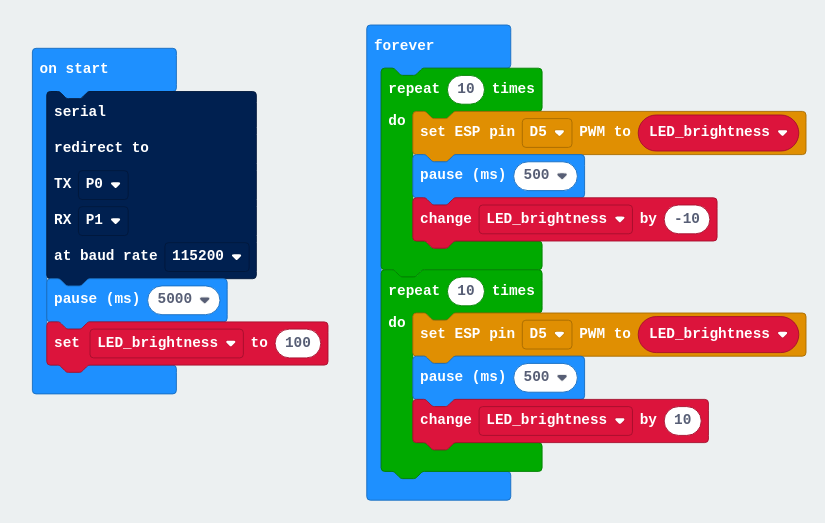
Figure 9 illustrates a short sketch to dim and brighten an LED connected to digital pin D5 on an 8266 Companion Board.
[Figure 9]
This group of blocks remained experimental at the time of writing. Please keep in mind that the MakerBit also supports I2C LCD devices. If these blocks do not satisfy you, then please consider using your LCD device with the MakerBit instead.
These blocks for the 8266 Companion Board support only LCD devices that have 16 character positions on each of two rows, which we may refer to as the 1602 format, and that connect via the I2C protocol. Adding support for the 2004 format devices (4 rows having 20 characters each) is a priority for future development.
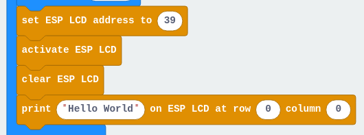
Figure 10 illustrates the four blocks in the LCD group. You can try running it as a demonstration, too.
[Figure 10]
This block tells the 8266 where to look on the I2C "bus" to locate the LCD device. 39 is a good first guess. If that does not work, try 63.
Send this command before you send the next one to actually initialize the LCD device.
A Brief Introduction to I2C Addresses
The I2C protocol permits many devices to share one physical connection. Devices must have a unique "address", which is a number between 0 and 255. The manufacturer puts that number into the device. You need to know it. Here is the good news: many LCD displays of the 1602 variety use either 39 or 63 as their I2C address.
It is beyond the scope of this article to go any farther into the details about the I2C protocol or I2C device addresses. Sorry, that's a subject worthy of a good search engine and a long afternoon with nothing better to do.
This block creates an "object" in the 8266 representing the LCD device having the I2C address given in the previous command. Send this command before you try to interact with the LCD display.
This block "erases" any characters visible on the LCD display and leaves the display empty.
The image above illustrates commanding the 8266 Companion Board to display text, "Hello World" on the top row (row zero) beginning in the left-hand position (column zero).
Count the characters in the text you send for display, to be sure they will not run past the right-hand position of the row (column 15). This article does not attempt to predict what might happen if you send characters off into the void that way.
- for PXT/microbit

