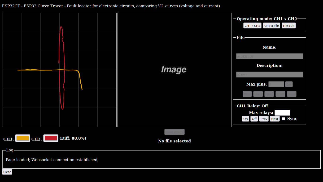
Fault locator for electronic circuits, comparing V.I. curves (voltage and current)
Operation based on this project: Curve Tracer ATmega328
Note: Work in progress, just demonstrative, not functional, sorry.
- Visual interface via browser (HTML page)
- IP address location via mDNS (esp32ct.local)
- Automatic/Manual test path selection
- Multiple test impedances (x1, x2, x4, x8)
HTML page (ESP32 Webserver, http://esp32ct.local/):
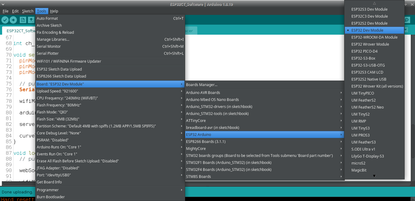
Upload procedure:
- Select "ESP32 Dev Module" board
- Select the "Erase All Flash Before Sketch Upload" (ENABLED) option
- Click the "Sketch (Menu)" > "Upload (Ctrl+U)" button
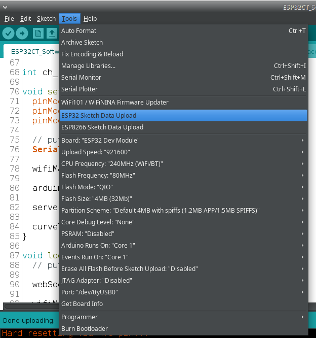
- Click the "Tools (Menu)" > "Esp32 Sketch Data Upload" button
WiFi network configuration:
- Log into the "AutoConnectAP" network, password is "password" (Active time is only 30 seconds)
- Open IP "192.168.4.1" (http://192.168.4.1) in internet browser (Do not use https://)
- Click "Configure WiFi" button
- Select your existing WiFi network
- Enter your WiFi network password
- Click the "Save" button
- Wait a while for the ESP32 to restart and log into the network, this can be monitored in the Serial Monitor of the Arduino IDE "Tools (Menu)" > "Serial Monitor (Ctrl+Shift+M)"
- Open "esp32ct.local" (http://esp32ct.local) address in internet browser. You can use the IP address entered in the Serial Monitor, or in an IP locator with mDNS support (Mobile devices may need an IP locator with mDNS support)
Arduino IDE - ESP32 board:
Uploading the Data Folder to the ESP32 (Webserver):
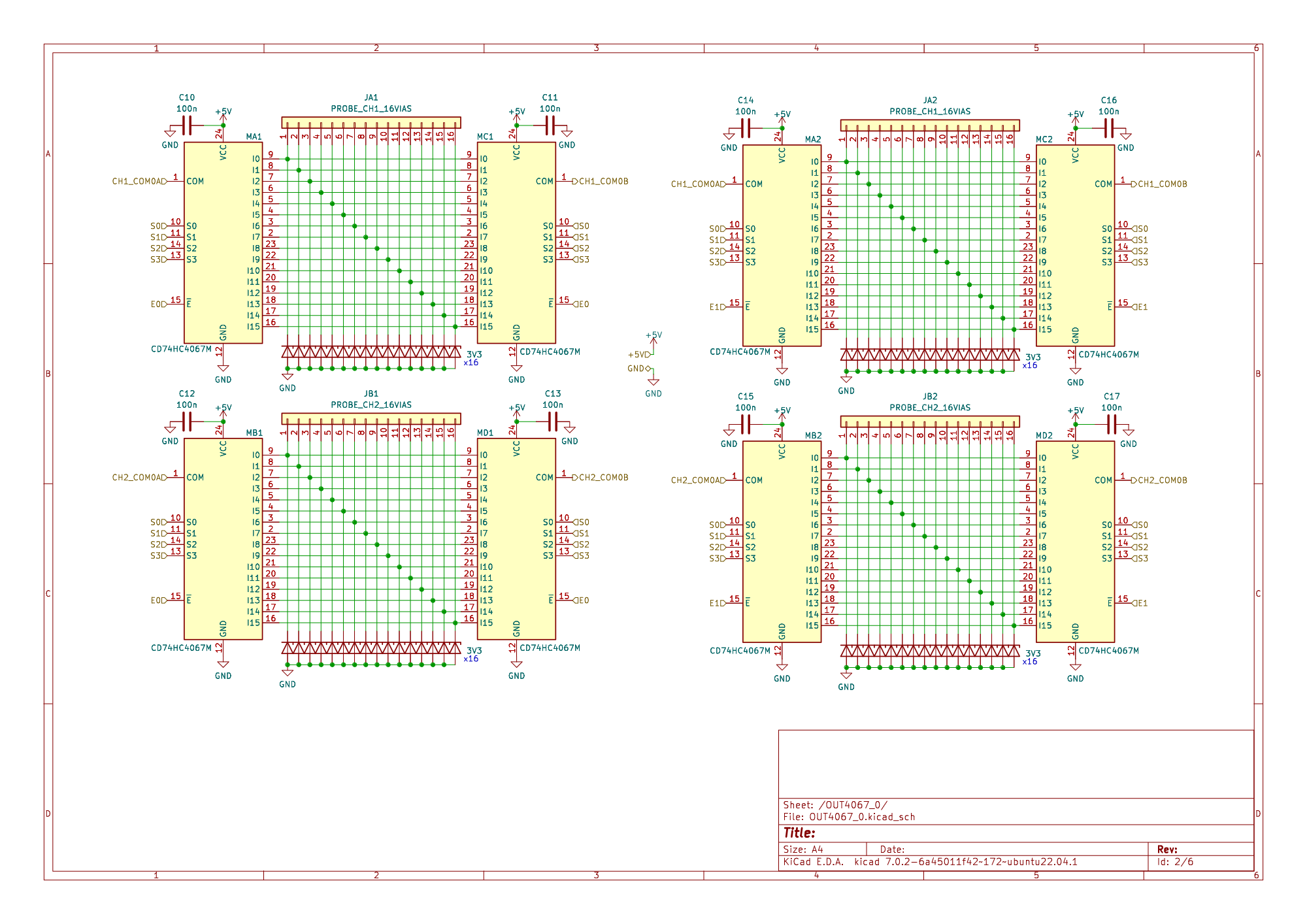
- Total 160 test tracks for each channel (Ch1: 160 probes, Ch2: 160 probes)
- Analog output via the ESP32's internal DAC
Main:
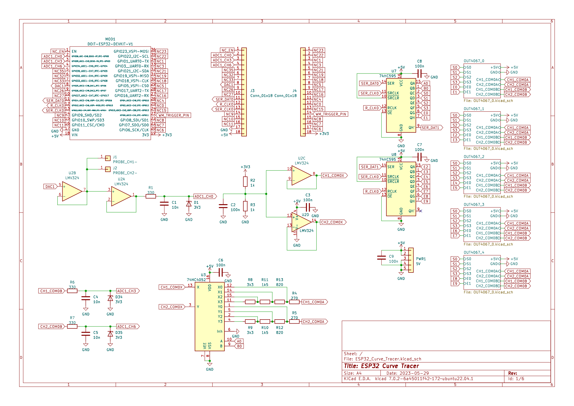
Expansion of probes:
IC 74HC4067 can be found under the code HP4067, and there is also a board already assembled with this IC:
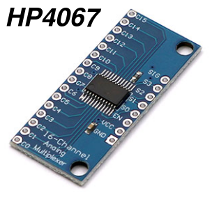
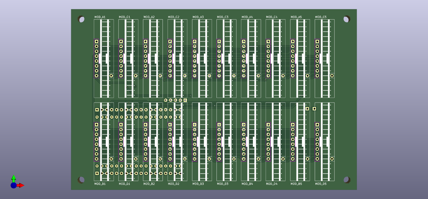
Using this HP4067 PCB board can be simpler to design:
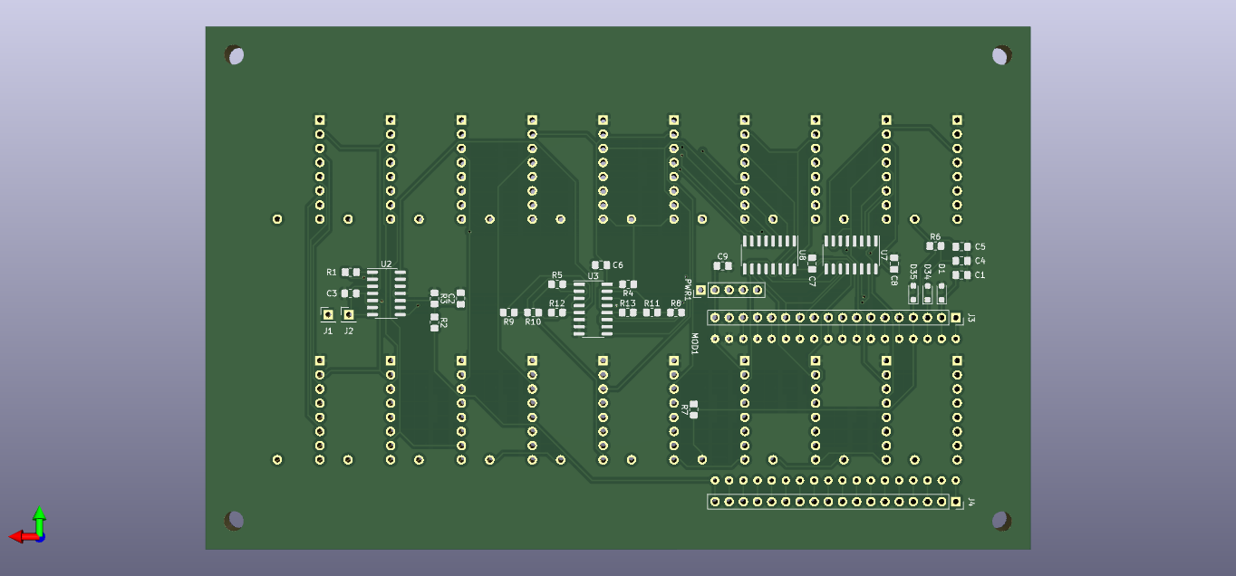
As there are empty spaces between the modules, the ESP32 and other components can be on the other side of the PCB:
Notes:
-
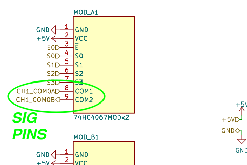
In this case, using HP4067 boards, each 74HC4067MODx2 module is made up of 2 HP4067 boards and the 16 zener diodes, present in the complete schematic.
-
On the 74HC4067MODx2 module, pins C0 to C15 are interconnected, as well as pins VCC, GND, EN and S0 to S3. Only the SIG pins are separated, and on the PCB they appear with pins 8 and 9.
Released under CERN OHL 1.2: https://ohwr.org/cernohl
This library is free software; you can redistribute it and/or modify it under the terms of the GNU Lesser General Public License as published by the Free Software Foundation; either version 2.1 of the License, or (at your option) any later version.
This library is distributed in the hope that it will be useful, but WITHOUT ANY WARRANTY; without even the implied warranty of MERCHANTABILITY or FITNESS FOR A PARTICULAR PURPOSE. See the GNU Lesser General Public License for more details.
You should have received a copy of the GNU Lesser General Public License along with this library; if not, write to the Free Software Foundation, Inc., 51 Franklin St, Fifth Floor, Boston, MA 02110-1301 USA