Need more information #2
Comments
|
Hello jnsbyr, thanks for your great job!
thanks a lot! |
|
Here is a list of the components that are not obvious from the schematic:
|
Please have a look at the schematic. It shows a block named "Control Panel Bus Tap". It should imply that the circuit is connected in parallel. In the description above this is mentioned explicitly "the original control panel and an additional remote control unit can be attached in parallel to the mainboard because the signalling supports a multi-drop architecture for listening". You may also have look at the top left of the schematic from Geoffrey. Hope this helps. |
|
Application note for the assembly of the y splitter case The part mentioned in the table above is tiny in comparison to the dimensions of the cable. The drill holes I used are a little smaller than the cable diameter to make them self sealing. Originally I planned to fill the case with epoxy to prevent the cables from being pulled out accidentality and to make it waterproof. But the fit was so tight that it was not really necessary. The cable ends need to be soldered together. To prevent a short circuit the open ends must be isolated again, e.g. using shrink tubing. If you don't intend to spend more than an hour on this item, use a case with a volume at least 3 time larger instead. You might even skip the soldering if you use a ready to use connector with screws or clips. |
|
Thanks a lot for the partlist. Did you use the original cable (mainboard <-> controle panel)? |
|
Yes, please have look at the photo of the
|

|
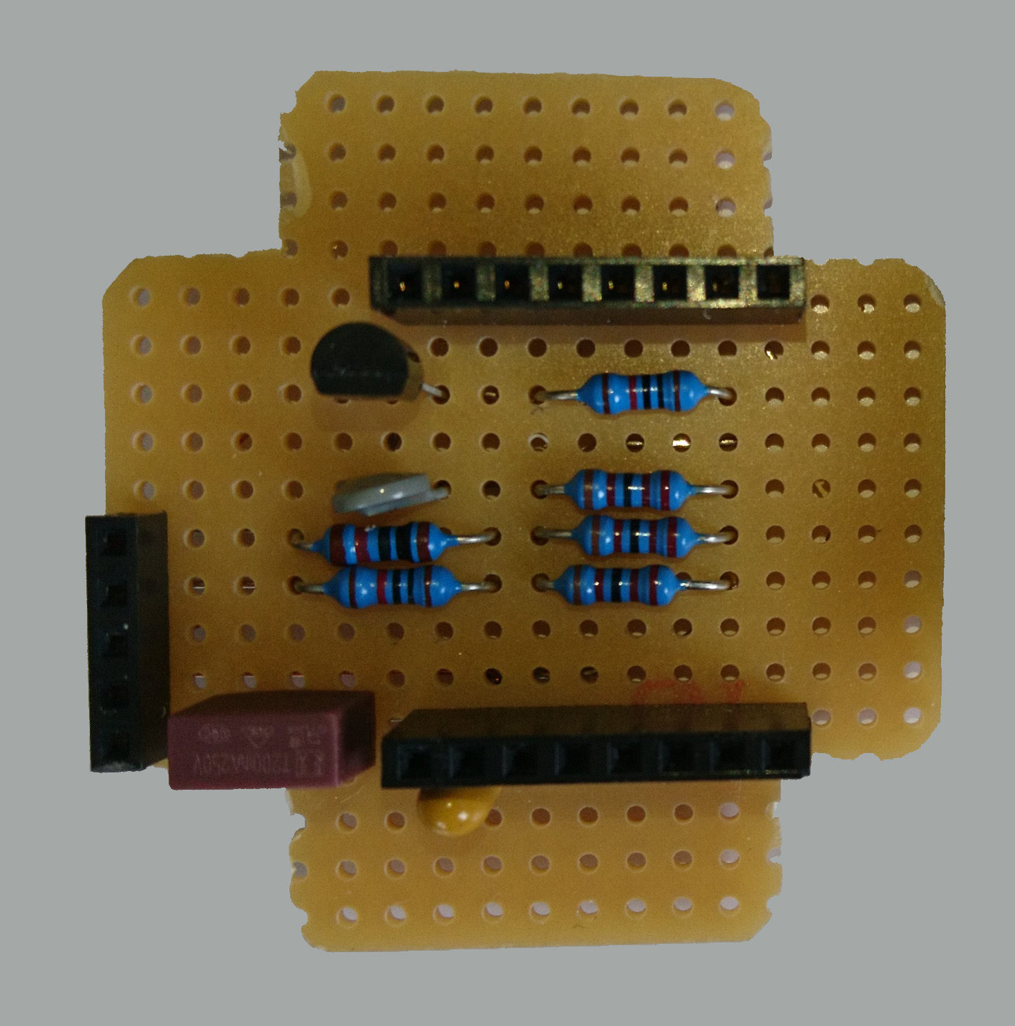
@PaTiTan: But what is this grey thing? https://user-images.githubusercontent.com/69749534/120898657-164df300-c62c-11eb-9e0d-9b58223c1025.png
You might have guessed by elimination that this must be the NTC. You can also use the link in the component table for another image of the same component. NTCs come in various makes and sizes. I chose this because it was cheap and comparatively robust (large). Any other 10k NTC will do.
|
|
The "command" dont appear so do it myself but i dont understand how work this command :
i just want to increase / decrease or put a value of température wanted. thanks for your incredible job !! |
This is an aspect of your MQTT server. Typically you need to define the MQTT topics that are to be send from the server to the client on the server side and these kind of topics typically contain the label "command". So here you need to enter all entries listed under "Subscribed Topics" in the readme. Once you have established a connection between the spa WiFi controller and your MQTT server you should be able to set any of the "Subscirbed Topics" on the server side. You can use serial debugging to check if the ESP8266 is receiving the MQTT command data.
With the topic "pool/water/tempAct" you have made the right choice. It is the actual water temperature. If you need to read back the last temperature setpoint then use "pool/water/tempSet" instead. The spa WiFi controller will send actual values after the connection is established to the MQTT server and to the spa mainboard. The setpoint temperature will stay undefined after power up of the spa Wifi controller until it is set for the fist time. |
In the schematic there is an abstract drawing of the plug titled "PureSpa Plug (M)" in the bottom right corner. The "M" stands for "male" and such a plug should have pins. The schematic shows the plug from its front side. So, looking at your images of the two plugs, the left one would be the M-type (with the contact pins missing) while the right one would be F-type. The socket in the Intex pump housing is the F-Type while the Intex control panel cable has a plug with the M-Type. |
|
maybe use this from diyscip ;) anyway, THANK YOU SO MUCH for you awesome great work ! you can close this issue :) |

|
@PaTiTan ... exept for ordering temperature with Jeedom via jMQTT
Thank you for your feedback, I am glad that you like this project.
The drawing of the plug from Geoffroy is good, but I didn't want to copy it
and I am not much of an artist myself.
You say that setting the temperature is not working for you. That's sad
because that was one of the major reasons I started this project. I cannot
help you with anything that is Jeedom specific, but if you are interested
in making this work I will try to help. First you must establish if the
MQTT command for the setpoint temperature reaches the WiFi controller.
Connect TX+GND of the ESP8266 to an TTL/USB converter connected to your PC
and open a serial terminal (e.g. PuTTY) with the serial parameters
74880/8/N/1. Every time you send an MQTT command from Jeedom you should see
a serial output looking like "set: <topic>: <value>". If not, the problem
is probably on the Jeedom side. If the topic "pool/command/water/tempSet"
is received and the value looks OK then contact me again.The value must be
an integer number, it should not contain a decimal point.
|
|
Tanks a lot, it was Jeedom MQTT :) Thank you so muck, you are the best!!! |
|
Hello jnsbyr |
|
@JonOLinux You could use a tool like KiCad and design your own PCB - but really, you don't need it. The circuit has only a few component and you need to solder anyway, so adding a few wires on the backside of the perfboard should be no big deal. It only takes a little longer than using a breadboard. |
|
Ok, I will do it.
Thank you for your help.
…________________________________
From: Jens B. ***@***.***>
Sent: Tuesday, June 15, 2021 10:38:03 PM
To: jnsbyr/esp8266-intexsbh20 ***@***.***>
Cc: Jonathan Giordano ***@***.***>; Mention ***@***.***>
Subject: [External] : Re: [jnsbyr/esp8266-intexsbh20] Need more information (#2)
@JonOLinux<https://urldefense.com/v3/__https://github.com/JonOLinux__;!!GqivPVa7Brio!O99VtKLRWvRceyEWl5DWsHrxwvUZkewdCjTXTteNXGo99NRrE7o9v1TDppLbgUlagCaOqA$>
Sorry, I cannot help you in this respect. Please read the Readme.md again. This project was started primarily as a proof of concept. I have not designed a PCB but used a breadboard for the prototype. It is working for me and there is no necessity for me to replace the breadboard with a PCB.
You could use a tool like KiCad and design your own PCB - but really, you don't need it. The circuit has only a few component and you need to solder anyway, so adding a few wires on the backside of the perfboard should be no big deal. It only takes a little longer than using a breadboard.
—
You are receiving this because you were mentioned.
Reply to this email directly, view it on GitHub<https://urldefense.com/v3/__https://github.com/jnsbyr/esp8266-intexsbh20/issues/2*issuecomment-861814804__;Iw!!GqivPVa7Brio!O99VtKLRWvRceyEWl5DWsHrxwvUZkewdCjTXTteNXGo99NRrE7o9v1TDppLbgUlrGwq25A$>, or unsubscribe<https://urldefense.com/v3/__https://github.com/notifications/unsubscribe-auth/AMWUNMP7XELU7VUKS7KYIQLTS622XANCNFSM452WSPGQ__;!!GqivPVa7Brio!O99VtKLRWvRceyEWl5DWsHrxwvUZkewdCjTXTteNXGo99NRrE7o9v1TDppLbgUmjxRr5kw$>.
|
|
@JonOLinux |
|
Hi @jnsbyr Could you share a picture of the backside of the perfboard and how it's soldered together as a reference? I'm trying to understand how to connect all components in the picture (https://raw.githubusercontent.com/jnsbyr/esp8266-intexsbh20/master/assets/Perfboard.jpg) in a clean manner without unwanted interconnections. |
|
Hope the picture I was able to make will help. The left is still left but the bottom of the top side picture is the top of the bottom side picture. A 3D picture of the perfboard wiring would be better suited, but alas, that's not done with a click. There are a total of 4 isolated thread wires for crossovers, all other connections are without crossovers or use pad to pad soldering. I tried to make use of all the wires that come with new components. I a few cases it was enough to just bend them first and cut them off at the next component pad.
And here is a picture of the open case that shows how the M12 cable connects to the board:
|


|
Many thanks, this is really helpful! |
|
Hello, could someone tell me more about the tendal capacitor? Tantalum capacitor, 10 µF, 16 V, RM 2.5 What voltage should the capacitor have? https://www.reichelt.de/tantal-kondensator-10-f-16-v-rm-2-5-tantal-10-16-p20332.html |
Looking at the schematic, the cap is connected to +5V nominal, might be around +5.25V for real. |
Hello,
You are doing a great job.
Can you give us the list of components?
Also general diagram of all the architecture because I do not know if your module is in parallel or in series.
Thanks
The text was updated successfully, but these errors were encountered: