A home project to play around with an Arduino and some woodworking. An automatic BMX start gate with:
- Electromagnetically controlled gate
- Standard UCI BMX start sequence including voice, lights and random delay
- Timing of the rider passing the control box via an ultrasonic sensor
- Speaking and display of the time
It can all be controlled by the rider and/or via a remote start button.

The main components are:
This is a wooden structure of approximately 2000mm total length, 500mm height and 680mm width. The frame is built from various rough cut timber pieces and topped with plywood. The gate part is 375mm long and hinges upwards via two heavy duty door hinges. The 375mm gate is tall enough to use the gate with up to 24" wheels.
I don't have any detailed plans for the ramp itself as I mostly made it up as I went along but there are plans for other similar ramps that can be found on the internet. This was my original sketch:
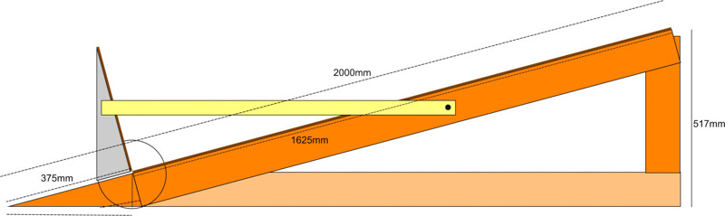
The ramp originally used a manual release mechanism like this where the gate catch remains in place by friction caused by applying pressure to the gate. One pressure is released, the catch releases and the gate falls. With practice, a snap back action can be used to release the gate. I soon wanted something a little more advanced though so decided to build an electromagnetic release mechanism.
An arm is attached to the gate with the "suction plate" of an electromagnetic door catch attached to the other. The main part of the electromagnet part of the door lock is statically attached to the side of the ramp. When powered by 12V and the gate is lifted such that the suction plate meets the electromagnet, gate is locked in place. The electromagnetic door lock I used has a claimed holding "force" of 180kg when powered by 12V and approx 400mA.
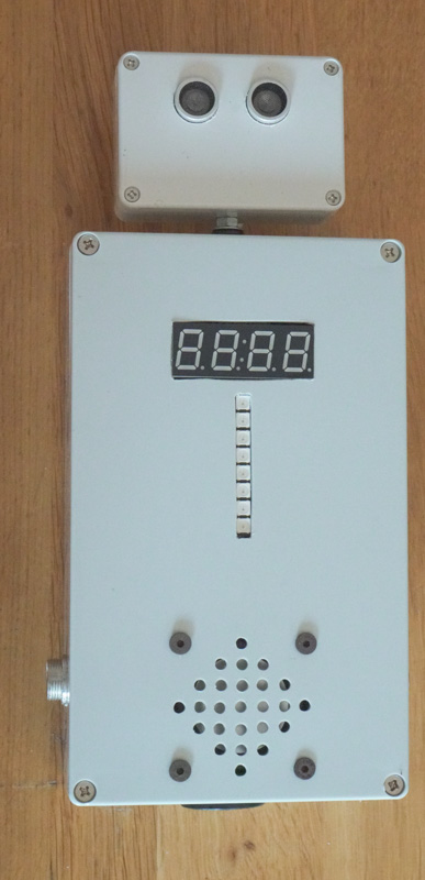
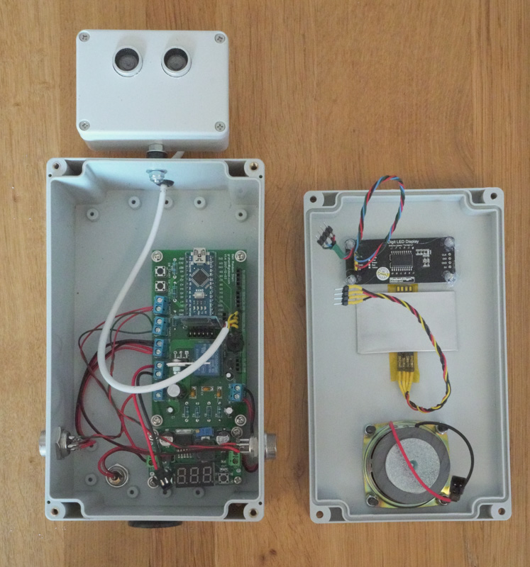
The controller box houses the electronics, display and sensors. The box powered via an external 12V source. 12V is used to drive the electromagnet and the speaker. A voltage regulator board is used to step the voltage down to 5V to drive the Arduino controller and associated electronics.
An off the shelf adjustable step-down voltage regulator board was used, set to 5V, similar to this
An Arduino nano is used as the main controlled. It uses an SD card module to hold the audio files for the speech.
Interfacing with the I/O pins of the Arduino are:
- An SD card reader, plugged into the SPI on the Arduino
- A TM1637 based 4 digit 7-segment display to show the elapsed time
- An Adafruit Neopixel compatible 8 LED strip for the start lights. Or, separate LEDs can be used for the red, amber 1, amber 2 and green phases of the start sequence; the source code is compatible with both options. #define exactly one of: USE_LEDS or USE_NEOSTRIP
- An ultrasonic sender and receiver, for timing the rider
- An audio output that is fed to the audio amplifier circuit
- "Start" and "Reset" switches.
The Arduino nano, connections to the various perhipherals and audio amplifier are built into one bespoke printed circuit board (PCB). Designs for this PCB can be found in the pcb folder and online via the superb Easy EDA
The ultrasonic sender and receiver allow the passing a rider to be detected. The Arduino code measures the distance detected from the receiver during the light sequence state and stores this as a reference. During the timing state of the loop it looks for the measured distance to be less than 2/3rds of that measured previously for a contiguous 20ms in order for the beam to be broken. In practice, if the rider is within approx 1.5m of the detector, the timing appears reliable.
The audio amplifer takes the output from one of the Arduino pins and amplifies it to drive a speaker, using the 12V rail of the power supply. The amplifier is based on a TDA2003L-TB5-T Single Channel amplifier IC and reference circuit.
The micro SD card holds the audio files used for the speaking the measured time. Copy all the files within the sdcard/ folder to a FAT formatted micro SD card.
In addition to the electromagnetic door lock, the ramp has two push buttons and an LED. The LED is connected in parallel to the electromagnet and simply indicates when the electromagnet is armed.
A start (green) button arms the electromagnet then when pressed again, initiates the start sequence.
A reset (red) button cancels the start sequence and disarmds the electromagnet.
The ramp and control unit are connected via a length of 4 core cable terminated with 4 pin connectors. The 4 wires carry:
- 12 V
- Ground
- Start switch signal
- Reset switch signal
The switches are activated when a connection to ground is made. By placing additional connectors on the ramp and control box, remote switch units can be added to allow the sequence to be controlled by a non-rider.
The Arduino source in the arduino/gate_seq folder is built with the Arduino Integrated Development Environment (IDE). gate_seq.ino contains the bulk of the source. Read this file to understand the library dependencies, pins used and configuration options.