-
Notifications
You must be signed in to change notification settings - Fork 21
UEC Utility Sheet
The Utility Expression Calculator (UEC) is a Java package that reads and interprets an Excel workbook; the workbook specifies and identifies input variables for a nested or multinomial logit model. The UEC Data Sheet defines the data files input to the model, including zonal (vector) data and skim (matrix) data. The UEC Utility Sheet specifies the structure and utility expressions of the model.
The UEC Utility Sheet has three sections:
- The first defines the nested or multinomial logit model structure.
- The second sets Tokens that can be used in subsequent utility expressions.
- The third contains the actual utility terms, generally consisting of a variable and coefficient specific to one or more alternatives.
Each of these sections are described in more detail below.
The first row in the UEC Utility Sheet allows the user to identify the model defined in the sheet with a number (in cell B1) and a name (in cell C1), both for identification purposes only. Moving across the first row, cell F1 refers to the decision-making unit for which the model is applied. This field is only relevant for models that rely on person (in which case F1 would contain a "p") or household (an "h" in F1) table data per the UEC Data Sheet definition. For models that do not rely on this information, the default value of "h" can go unchanged. Cell H1 definies the number of alternatives in the discrete choice model. If a nested logit model, the number of nesting levels is specified in J1 and "NL" is placed in cell I1. If a multinomial logit model is desired, cells I1 and J1 should be left blank.
Next, each alternative is given a specific, unique identifying name, starting in cell G3 and moving down the row for each alternative. The specific name is "Alt"[n], where n is the number of the alternative. The fourth row allows the user to specify a string name for each of the alternatives (a short name should be used, as text logging files will use this name to report output in a pre-determined format).
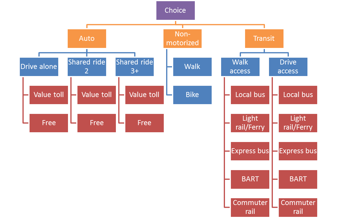
For a nested logit model, the next several rows, starting in row 5, define the nesting structure as well as the nesting coefficients. The two images below contain a UEC definition of a nesting structure and a graphical depiction of the same nesting structure. Row 5 must define the lowest level nest and identify each group with a unique integer, starting with 0. In the example below, each alternative stands on its own at the lowest level, so the alternatives are numbered 0 through 17. Row 6 in the example below defines the second lowest nest, identifying each group with an integer. Here, DAFREE and DAPAY share a nest, so each is identified with the integer 0; !SR2FEE and !SR2PAY share a nest, so each is identified with a unique integer (1, in this case). Row 6 defines the third lowest nest in a similar way, and so on. The Token in column B must be identified with the variable "nest[n]" where n denotes the nesting level.
Following the definition of the nests, the nesting coefficients are defined. The software knows these rows contain nesting coefficients because the Token column reads "nestCoeff[n]", where n denotes the nesting level. The example below shows the lowest level nest has a nesting coefficient of 1.0 (this is applied to the level at which each alternative is in its own nest -- a so-called dummy nest) and the highest level nest, which segments automobile, non-motorized, and transit travel has a nesting coefficient of 0.72.
An example of a UEC nesting structure:

And the corresponding graphical depiction of the nesting structure:

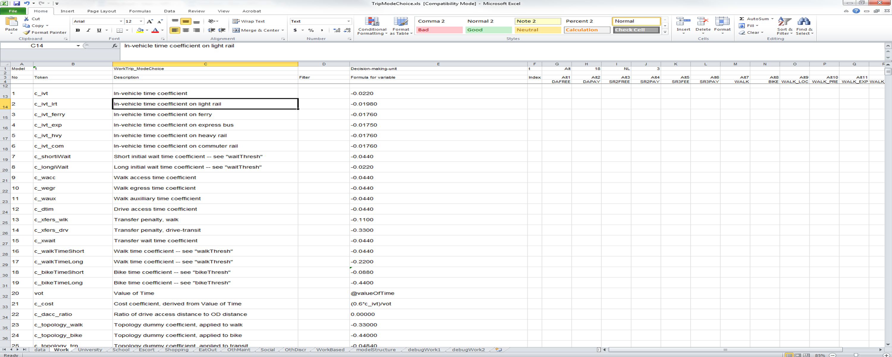
The next section of the UEC Utility Sheet defines variables, or Tokens, that are used in subsequent utility expressions. This section is optional, as the user may prefer to embed numerical coefficients in each of the utility expressions separately; using variables increases the readability of the file and also reduces the potential for typos. There must be one blank row between the nested logit model specification section and the beginning of this section. The "No" field must contain a unique, sequenced integer to let the software know that this row should be read and processed. The Token field defines a string that will contain the numeric value stored in the "Formula for variable" field. An example is shown below.
In the example, the Token "c_ivt" is being used to designate the coefficient on in-vehicle travel time and the value assigned to this Token is -0.0220. The Token "c_ivt" can be used in subsequent utility expressions.
Tokens can also be used to define variables stored in the Decision Making Unit (DMU) as described in the Utility Expression Calculator page. Below the variable @valueOfTime is being stored in the Token "vot". The @ symbol tells the user that the quantity is stored in CT-RAMP and that a getter function getValueOfTime() is a method in the DMU for this UEC. In this example, value of time is determined by drawing from a household-income-category-specific distribution for each person in each household. This is done within CT-RAMP and the results are stored in CT-RAMP for access by this and other discrete choice models.
Tokens can also compute formulas. In the example below, the coefficient on cost is a function of a traveler's value of time and the in-vehicle time coefficient. The software can perform calculations using C\C++ (Java) syntax.
Example UEC token definitions:

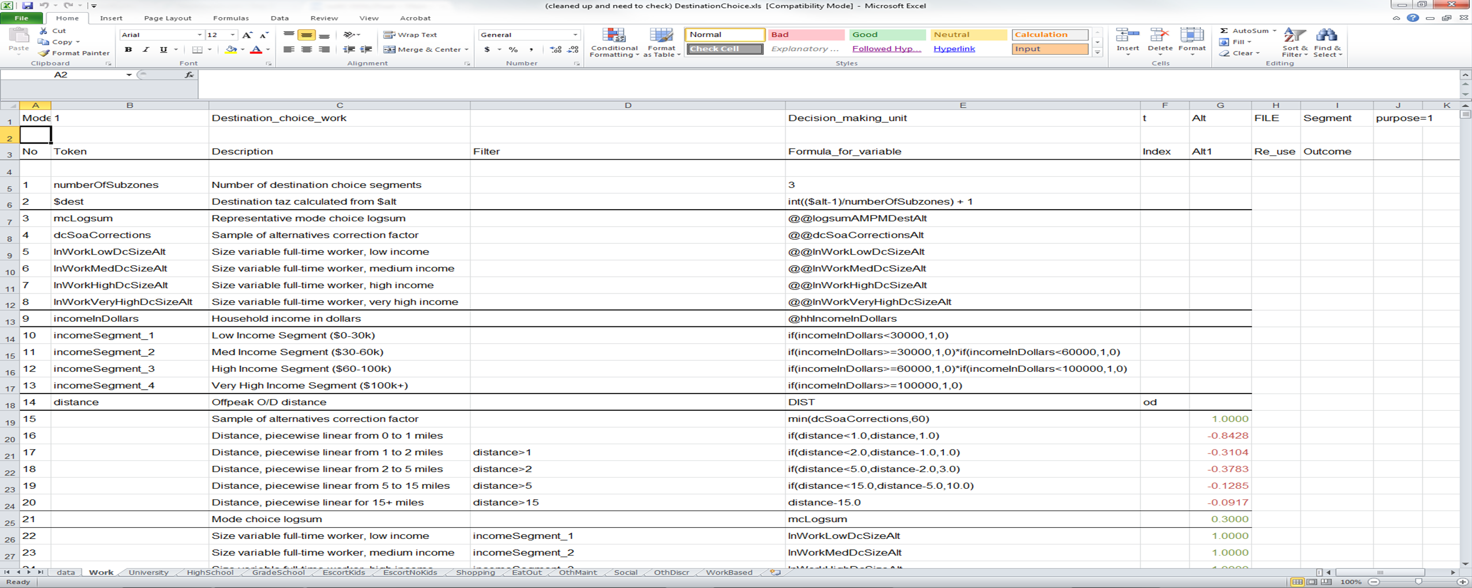
Discrete choice alternatives are defined in the UECs in one of two ways. In the first method, alternative-specific columns allow the user to define the utility expressions specific to each alternative. As presented in the two screen shots above, the example mode choice model has 18 alternatives, each of which has a separate column for introducing utility coefficients. This structure becomes infeasible when the number of alternatives in the model is large. For example, a destination choice model may select among thousands of alternatives. In this case, a file is used to define the alternatives. Below is a screen shot of a destination choice model. In the first row, the "Alt" keyword is followed by the "FILE" keyword, letting the software know that the alternatives are defined via a file. The UEC Data Sheet must then contain a table data entry with the "type" keyword set to "alternatives".
In this destination choice example, the number of alternatives is 1454 travel analysis zones times 3 (transit walk market) sub-zones for each travel analysis zones, for a total of 4362 alternatives. The alternatives, therefore, are numbered 1 through 4362. To extract out the destination travel analysis zone from this alternative, the key word "$alt" is used in the expression on the line numbered 2. The "$" is used to refer to an alternative within the UEC. By setting the result of the expression in line 2 equal to the keyword "$dest", the user is letting the software know that any calls to matrices with the index "d" should use this destination (for example, the call on the line numbered 14 extracts the distance from the matrix named DIST using the "origin", as set in the Java code, and the "destination" using the value computed in the line numbered 2).
The example below also uses the "@@" syntax, which refers to DMU methods that expect an integer argument -- the argument being the alternative number. So the "@@lnWorkLowDcSizeAlt" entry refers the user to a method in the DMU class named "getLnWorkLowDcSizeAlt" and this method expects an integer argument. The software indexes this data object using the "$alt" variable.
Example of UEC alternatives defined by file:

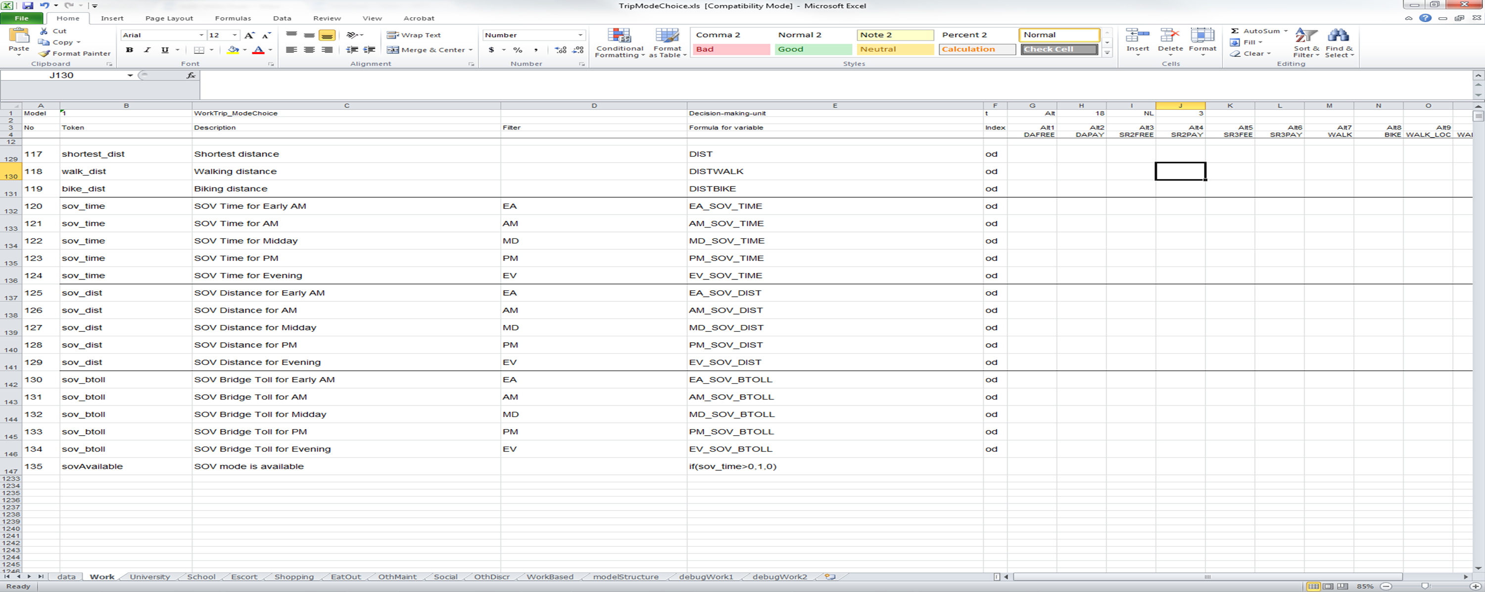
Below, another portion of the UEC demonstrates how the Filter column can be used. The Filter column allows certain expressions to be skipped if they are not relevant to the decision-maker for which the UEC is being solved. Below, a time of day filter is being applied in a mode choice model. The boolean variable "EA", which was defined as a token previously, is equal to 1 if the time period of concern for the decision maker is the "early AM" period and equal to 0 if the time period of concern is not early AM. On row 120 (the row for which column A has a value of 120), the Token variable "sov_time" is set to the matrix value EA_SOV_TIME (which defines a skim file on the UEC Data Sheet) if the "EA" token is equal to 1. If the Filter is false (i.e. a value of 0 or less), the calculations requested on this row of the UEC are ignored by the software.
The Index column, also used on Row 120, tells the software the manner in which values should be extracted from files specified on the UEC Data Sheet. The possible index values for matrices are as follows:
- "od", index by origin to destination;
- "do", index by destination to origin;
- "sd", index by stop to destination;
- "so", index by stop to origin;
- "ds", index by destination to stop;
- "os", index by origin to stop.
The user defines the origin, destination, and stop locations relevant for the decision-maker within the CT-RAMP software. The index "z" is used for vector data (i.e. flat files of TAZ-specific data).
Example UEC filters and indices:

The final section of the UEC Utility Sheet specifies the utility expressions that define each alternative. The software first evaluates the Filter column, if present. If the Filter column is empty or if it solves to true, the software than solves the Formula for variable field. This result is multiplied by the value in each of the Alternative columns (blank columns are zero). Each row that defines a utility value, therefore, defines a value for each of the alternatives. As calculations are made, a running sum is kept of the utilities for each of the alternatives. When all the rows are solved for, the software knows it has the complete utilities for each of the alternatives and returns an array of utilities to the CT-RAMP software. If the utility of a specific alternative is less than negative 500, the software considers this alternative to be unavailable. As you see in the rows numbered 958 through 962, a value of -999.00 is generally used to make an alternative unavailable if the criteria in the Filter and/or Formula are non-zero. Similarly, if the expression does apply to an alternative, a value of 1.00 is placed in the Alternative fields. This convention allows the user to quickly identify the terms that are relevant to each alternative.
Example UEC utility calculations:
